In my personal opinion nothing defines the concept of American air superiority as well as the
McDonnell-Douglas (now Boeing) F-15 Eagle. The days of single-role aircraft designed
for a specific purpose are now gone. Now that the emphasis is on budgetary constraints
and finding multiple ways to utilize equipment, we have aircraft designed to try and do all
jobs with a single airframe. Air superiority, ground strike, ground suppression, stealth,
everything rolled into a single airplane. The result is a few aircraft that do everything
marginally well and nothing exceptionally well. The Eagle was the last of the line.
The Eagle flies as few others do. The F-15A (and subsequent "C" version) Air Superiority
variant was designed from the outset as an air superiority fighter, and it's capabilities in
that arena are legendary. The F-15 Eagle has a perfect combat record of 101 victories
and zero defeats in its 30 year history
(Boeing Background).
Over 1,500 F-15's have been produced by McDonnell-Douglas / Boeing.
Take note of the gross aircraft weight and engine thrust numbers in the specifications table
below. The aircraft has a gross weight of 44,500 pounds and two engines providing a total
of 47,660 pounds of thrust. The Eagle was one of the first aircraft to achieve a thrust to
weight ratio greater than 1:1 which also made it one of the first aircraft able to accelerate
going straight up.
Although some variants of the F-15 will still be flying well into this century, the "C" air
superiority variant is destined to be replaced by the F-22 Raptor. There are five primary
versions of the F-15 Eagle:
- F-15A -- Single-seat air superiority variant (replaced by the F-15C)
- F-15B -- Two-seat trainer variant of the F-15A (originally the TF-15A)
- F-15C -- Single-seat air superiority variant (upgraded F-15A)
- F-15D -- Two-seat trainer variant of the F-15C
- F-15E -- Two-seat fighter-bomber or "Strike Eagle".
There are also international variants of the F-15 such as the F-15J and -DJ versions license-built
in Japan by Mitsubishi for use by the Japanese Self Defense Force and the F-15I in use by the
Israeli Air Force. The international variants have the same general configuration as
the US-built F15-C, -D, and -E variants.
On a historical note, the F-15 was the first military aircraft produced by McDonnell-Douglas
Corporation after the merger of McDonnell Aircraft Corporation and Douglas Aircraft on April 28,
1967.
This model is of aircraft number 78-0544. It was assigned to the 44th Tactical Fighter
Squadron, 18th Wing, USAF at Kadena Air Force Base, Okinawa circa 1993.
This Link shows some photographs of 78-0544 as the "44th Fighter Squadron Commander's Jet".
Here Is Another Page on the same site with some detail photographs of 44th Squadron jets. The photographs on the pages,
listed above were taken between 1993 and 1994 even though the copyright is 2000. This information came from a person
who flew F-15's from Kadena during that period and recognized some of the names on the jets.
| Manufacturer: |
Tamiya 1/32 scale McDonnell-Douglas F-15C Eagle
|
|
| Aftermarket: |
Cutting Edge Modelworks 32143 Exhaust Nozzles
Cutting Edge Modelworks 32056 ACES II Ejection Seat
Eduard 32056 PE Set - F-15C Exterior Detail Set
Eduard 32533 F-15 Formation Lights
Eduard 32532 F-15 Interior Set
|
|
| Finishing: |
This model has just been started however it will be finished in the "Mod Eagle" camouflage scheme
adopted for the F-15's in the early 1990's. The colors will be as shown in
These Photographs of 78-0544
as the 44th Fighter Squadron Commander's jet. The "Mod Eagle" colors are supposed to be
FS36176 Dark Grey and FS36251 Medium Grey, however those colors are much, much darker than the
photographs of the jets shown in the page above.
Testors Model Master number 1794 is supposed to correspond to FS36251, which is the lighter of
the two gray tones, and according to the color charts I've seen it is relatively
close to the standard. As far as a color for the actual aircraft it is quite dark. I
haven't come up with a good mix yet, but out of the bottle it is too dark.
Of course, this also depends on how and when you look at the aircraft! Take a look at these
three photos on Airliners.Net. They are all three of
aircraft 78-0496 (44th TFS from Kadena).
First Photo - Taken on March 17, 2005
Second Photo - Taken on March 19, 2005
Third Photo - Taken on March 19, 2005
Same aircraft and two of the photos taken on the same day. The difference in the shade of
the light gray color is obvious though.
|
|
| Build Started: |
July 18, 2005 |
| Build Completed: |
Under Construction |
Note that I have not been following the
instructions exactly in order so the photographs are not in any particular order. I
added them to this page as I finished a section or noticed something that needed to be
added to the page.
|
 |
 |
 |
All images above are links to larger photographs. Click the image to view the larger photo
August 4, 2005 -- I finally got SOMETHING
finished on this model! Not much, mind you, but at least I finished something. I
have several other items started, painted, or otherwise begun but this is the only item that
is more or less finished.
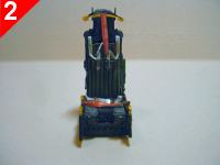
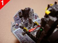
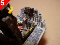
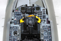
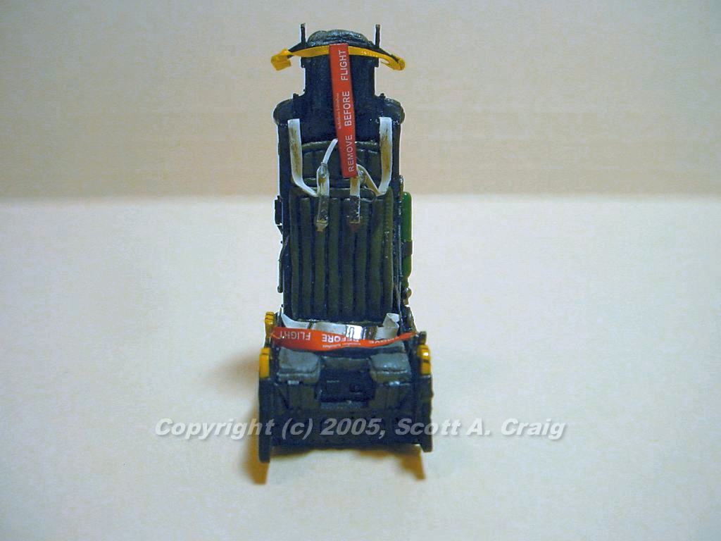
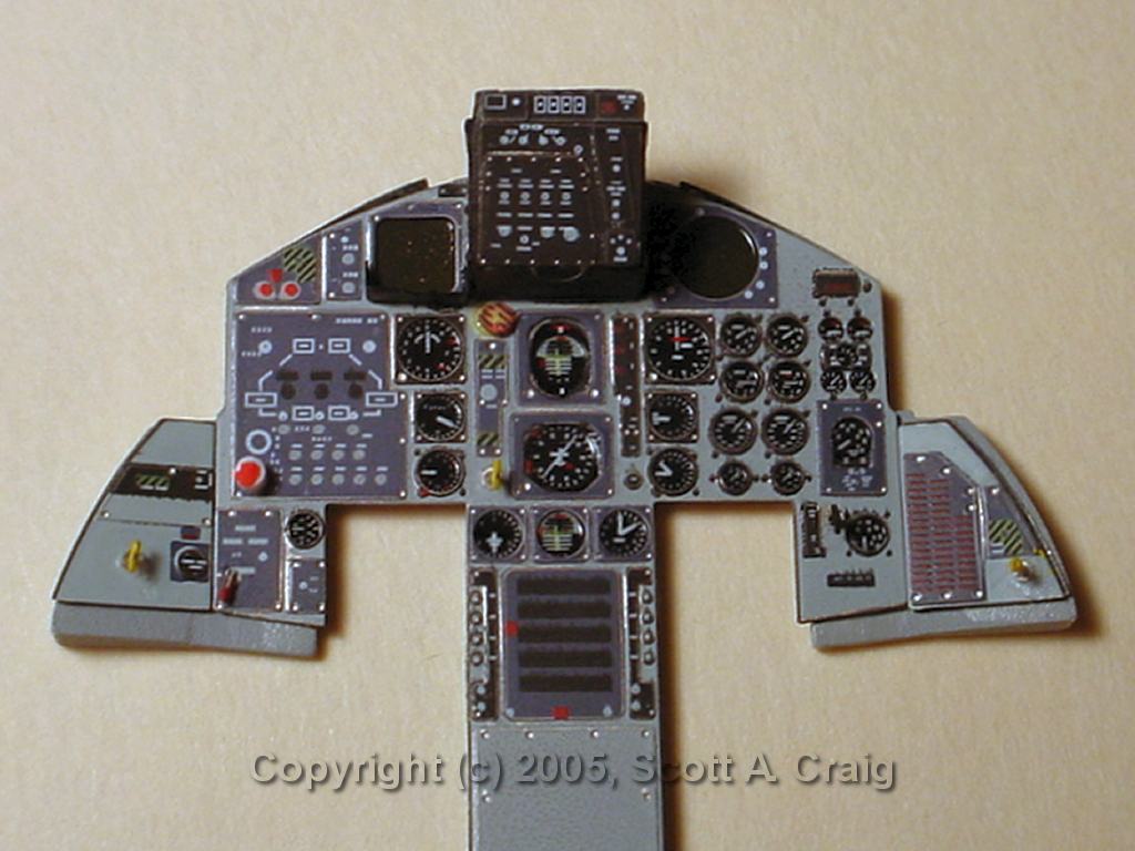
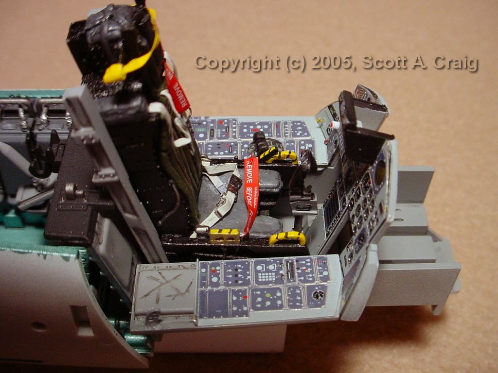
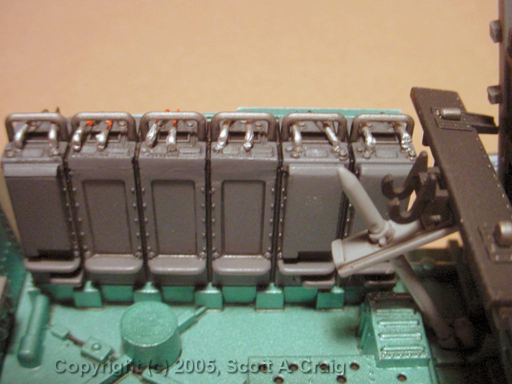
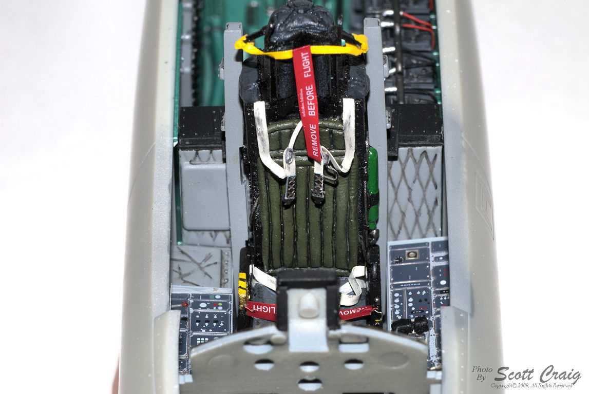
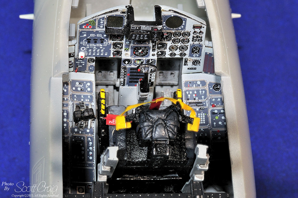
The harness in the front view (photo 2) looks like it has some olive drab paint smeared
on it. It doesn't. There is some dark gray drybrushing on the harness but it
isn't olive drab and it doesn't look like it does in that photo. Trust me, the
real thing looks right.
|
|
 |
 |
 |
All images above are links to larger photographs. Click the image to view the larger photo
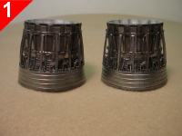
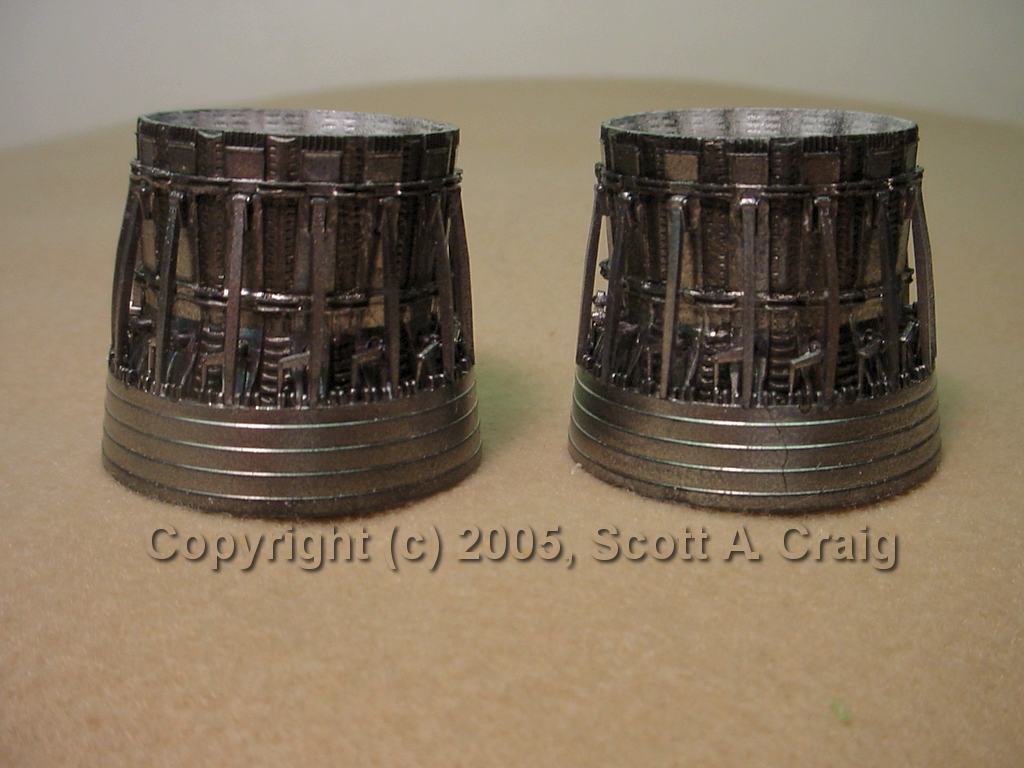
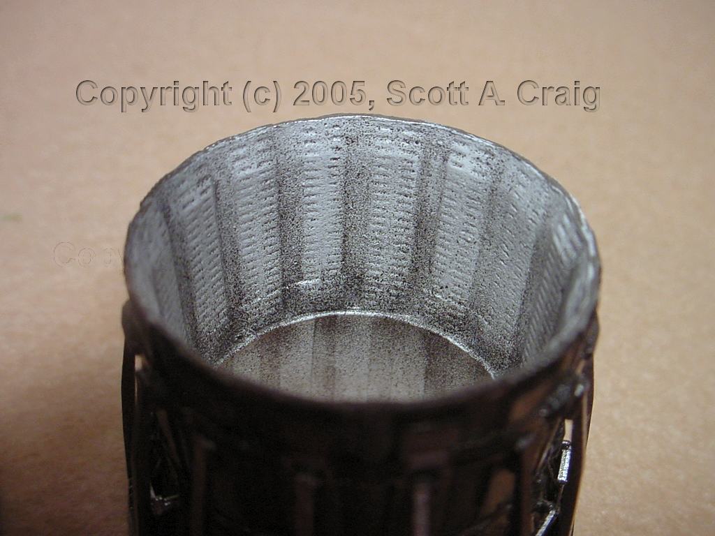
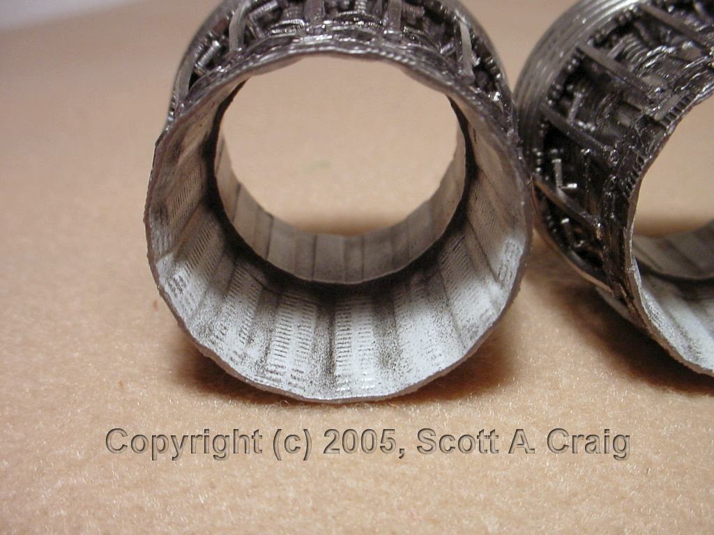
August 8, 2005 (Photos revised 09/15/2005) -- Above are the
Cutting Edge Modelworks 32143 Exhaust Nozzles They are painted with Alclad
Stainless Steel and then washed with a black acrylic wash. The insides were sprayed
flat white and then sprayed again with flat black with emphasis on the joints. They
actually look better in real life than the do in the photos because the paint doesn't look
as grainy on the real parts. Keep in mind that the openings are about the size of a
quarter so the photos are much larger than life.
I'm not sure what causes it, but this is the last time I use Alclad primer. I sprayed
the parts with primer, waited 24+ hours and sprayed a second coat. I then waited
another 24+ hours before spraying the Stainless Steel. After three WEEKS they still
feel sticky in places and I've had to be very careful handling them. There is no
reason for this since this primer is a laquer and should dry very quickly. Just
about every time I've used this primer I've had the same problem so I'm going to use
something else from now on.
|
|
 |
 |
 |
All images above are links to larger photographs. Click the image to view the larger photo
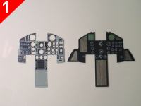
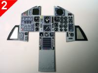
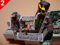
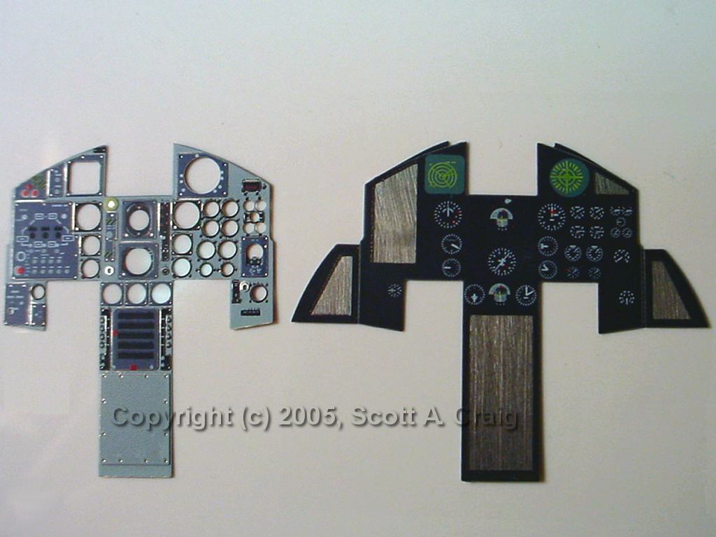
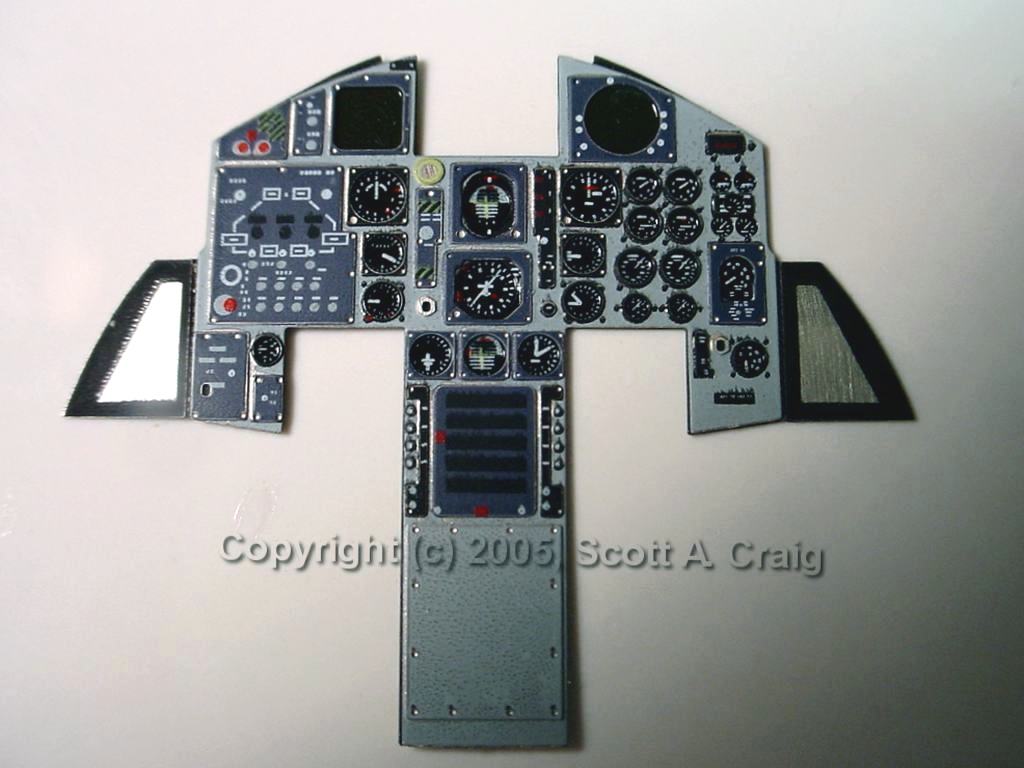
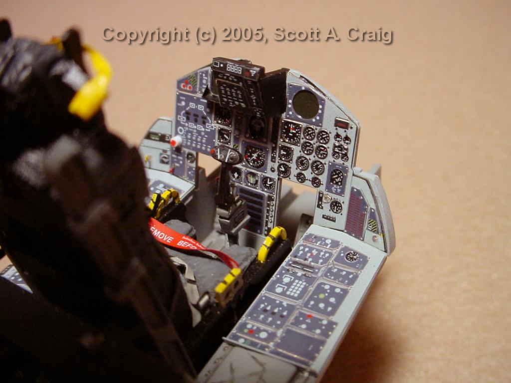
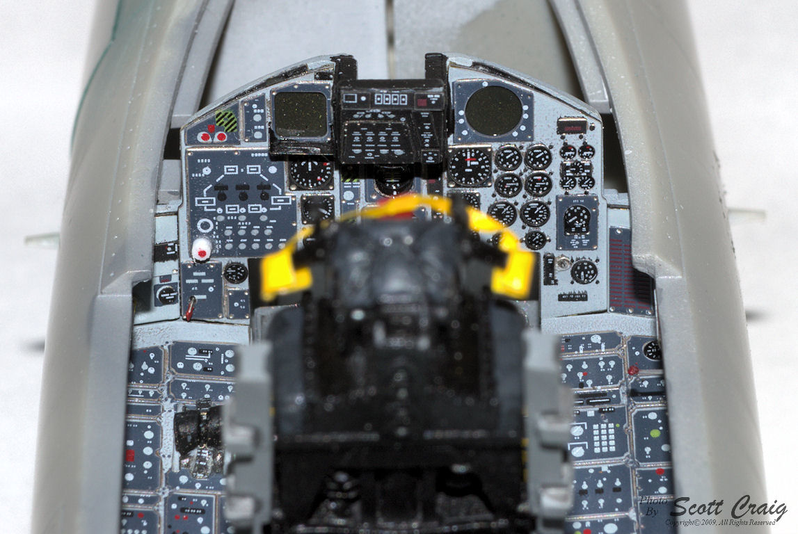
August 9, 2005 -- Above is the main instrument
panel of the
Eduard 32532 F-15 Interior Set partially assembled. As can be seen in photo 1
the panel consists of two layers of PE, one that is the instrument faces and one that is
the outside of the panel. The two are glued together to form the main part of the
panel which is then glued onto the kit panel. All of the detail on the kit panel
must be sanded off prior to assembly so the PE will lay flat on the panel. The
PE set also contains two triangular panels that go on each side as well as some
smaller pieces that I do not have assembled yet. The panel on the right of photo
1 looks like it has some wood-grained areas on it. Those are reflections from
something because those areas are bare metal.
Also as seen in photo 1 there are two screens at the top of the panel that are wrong
if the aircraft does not have the avionics energized. They show light colored
markings on them that would not be visible unless the systems were on. As can be
seen in photo 2 I painted them dark green.
Each individual instrument has received two coats of Future so far to simulate the glass
face of the instruments. I need to add a couple of more coats but when I took the
photos the Future that was there had not dried yet.
There is also a red "Dot" on the lower left side of the panel that is badly out of
register. It appears to be a jettison selector switch and needs to be extended
from the panel somewhat. I haven't fixed it yet but I will before the panel goes
in the cockpit.
Using color photoetch almost feels like cheating. I really enjoy doing cockpits
and it doesn't feel right not doing one. On the other hand the panel just really
looks too good not to use!
Update - 08/12/05 - Photo 3 shows the completed panel. Well, completed except for
the fact that when I looked at the enlarged photo I could see that I still need to work
on the "Red Dot" on the left side of the panel. That control is a raised white
selector switch with a red commit button in the center. I used a very short piece
of 0.040" styrene rod for the selector and put a dot of red paint on the end. I
must have smeared it a bit because it isn't centered on the rod.
|
|
 |
 |
 |
 |
 |
 |
 |
 |
 |
|
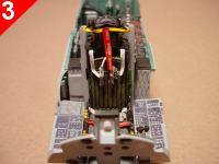
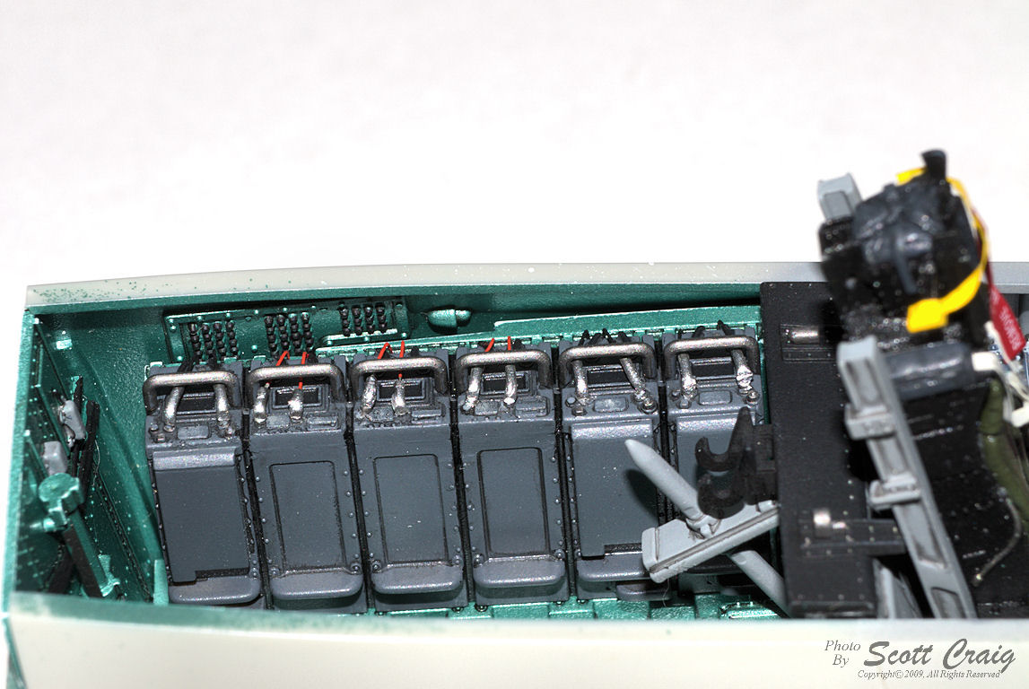
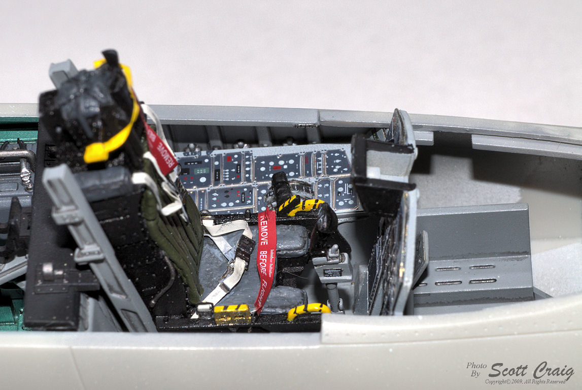
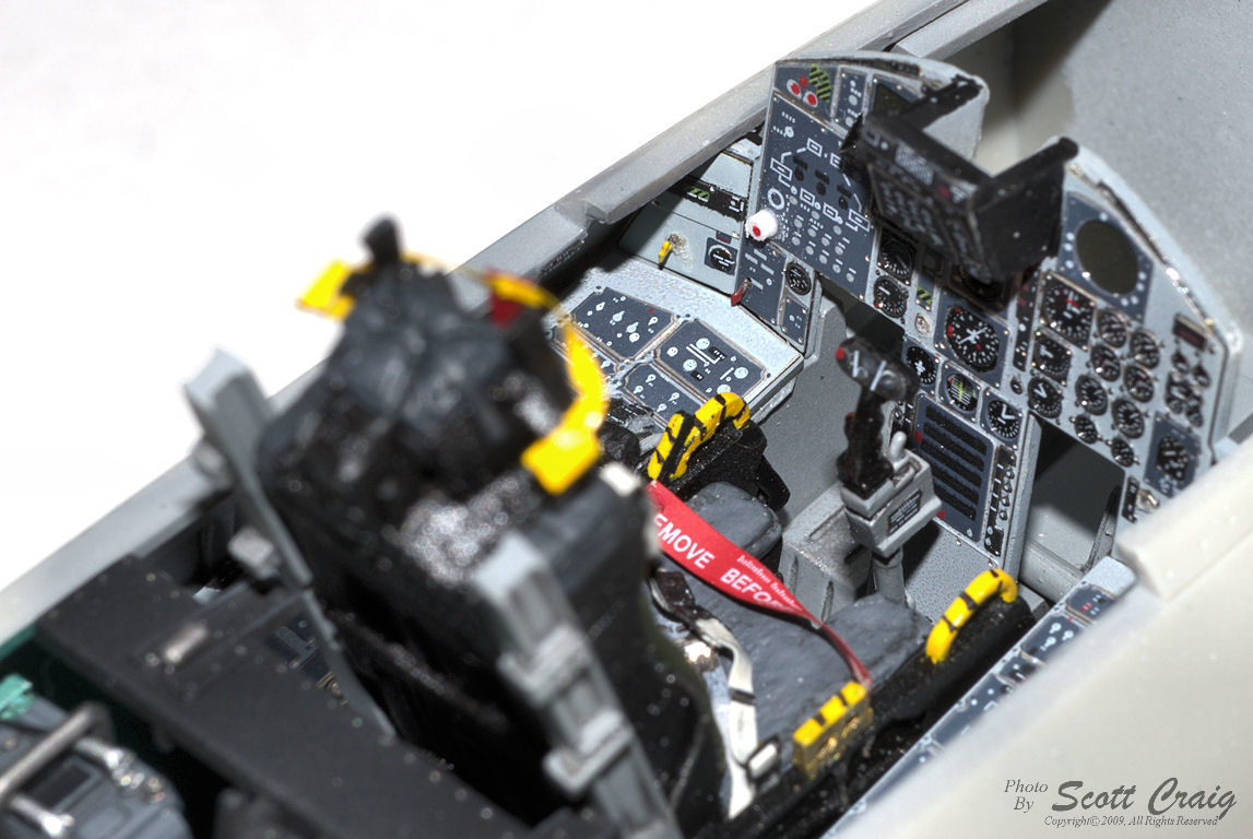
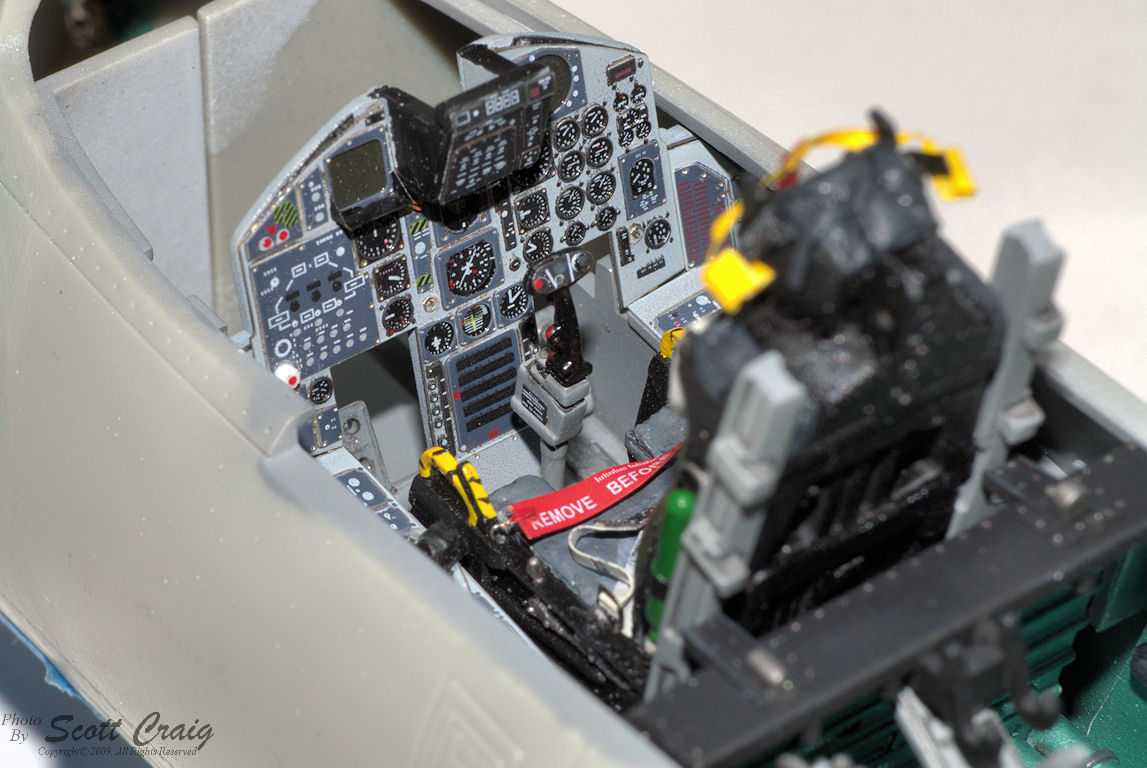
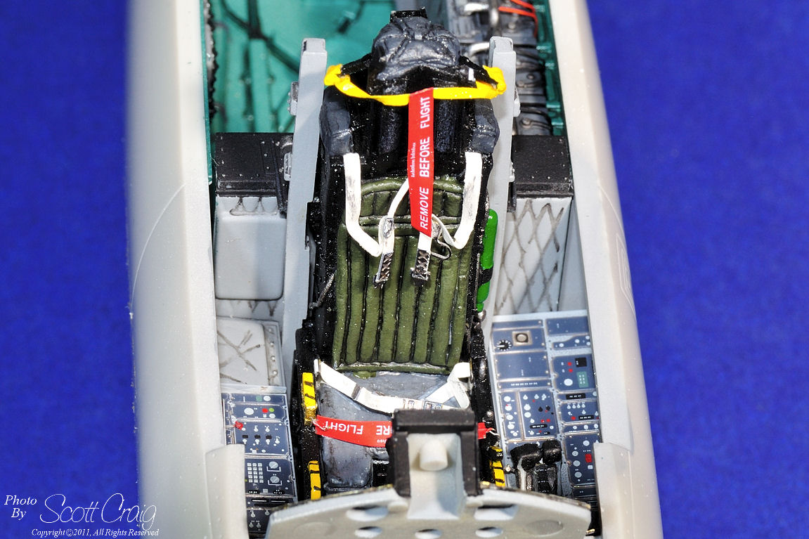
Update - 12/31/2009 and 12/04/2011 - Still no work done on this model in over 4 years, but I did take a few more detail photos
of the cockpit
|
 |
 |
 |
 |
 |
 |
 |
 |
 |
 |
 |
 |
 |
|
|
|
All images above are links to larger photographs. Click the image to view the larger photo
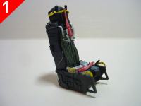
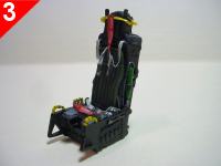
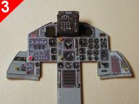
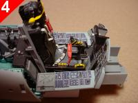
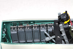
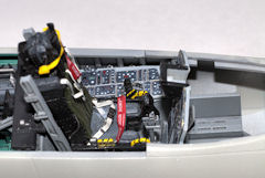
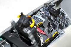
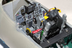
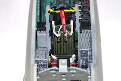
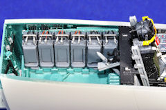
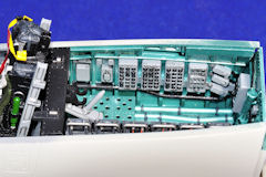
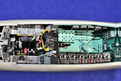
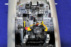
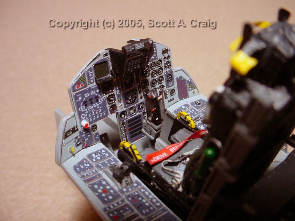
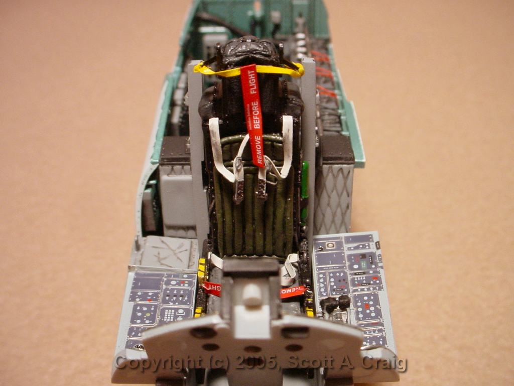
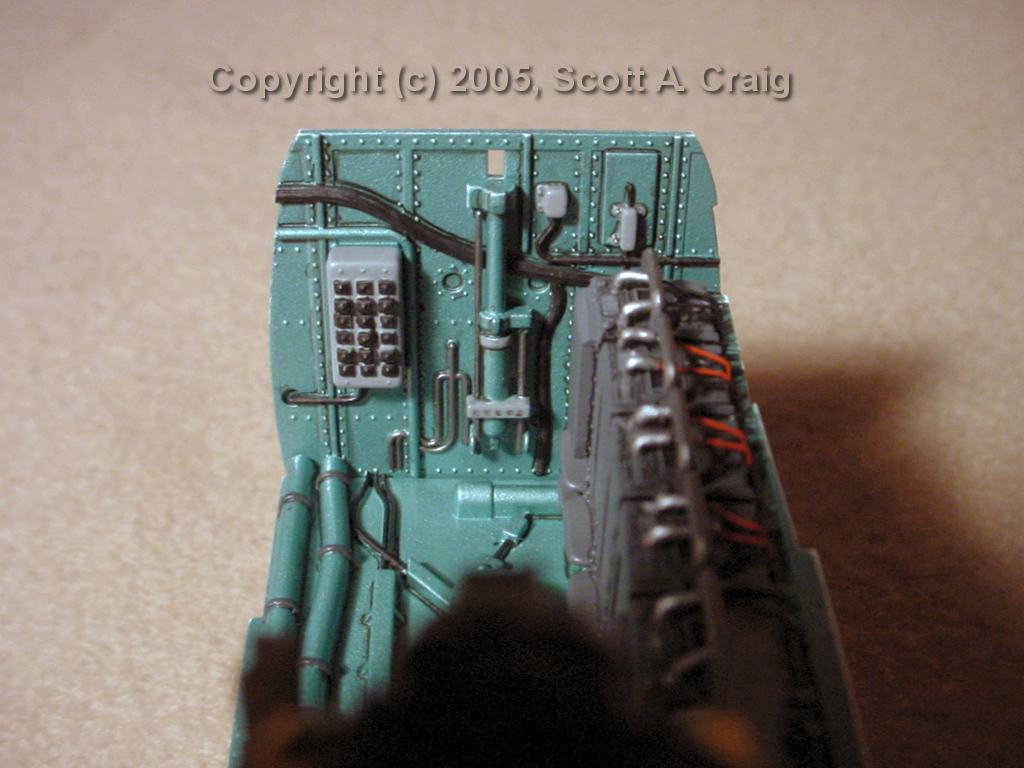
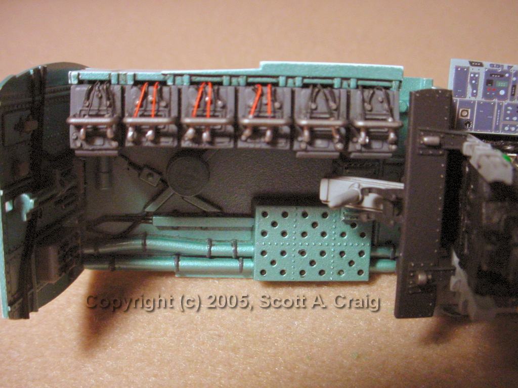
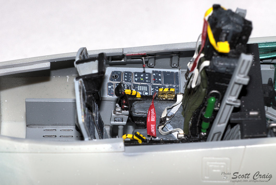
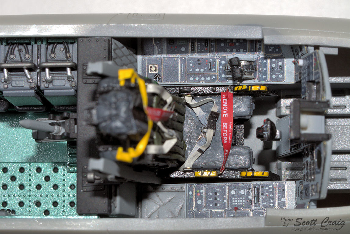
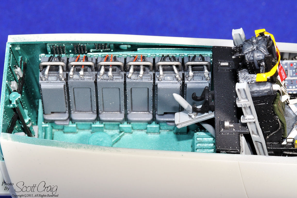
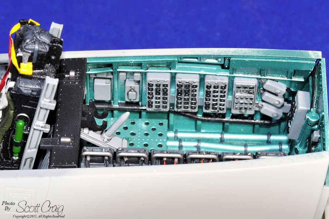
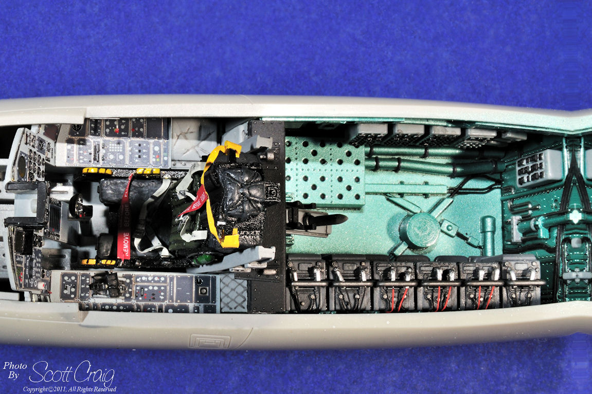
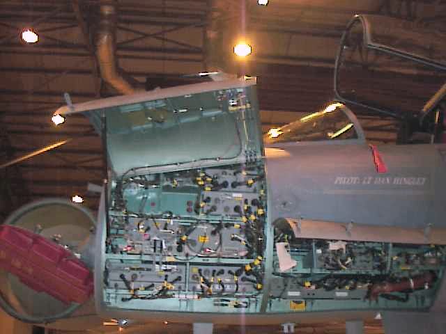
August 15, 2005 -- Here is the completed cockpit
and electronics bay. More or less completed anyway. I noticed in the photographs
a couple of places I need to add some wash and a couple of places that need some paint
touch-up. I also noticed some minor joints between the side panels and the main
panel that need a little filling. Call it 99% complete :)
There is one advantage to taking photos of models and posting them on a web site that I
had not envisioned until I started doing it. When viewed on a computer screen the
photographs are normally much larger than real life. This makes it much easier to
spot minor flaws that I would not otherwise have noticed. When I put photos on this
web site I notice things that I didn't see while building the kit. Things such as
paint flaws, areas of wash that didn't get cleaned up properly or areas that just didn't
get washed. Joints that need a little bit more sanding or filling, decals with
some silvering in them, and so on. The number of minor flaws I can find it photographs
that I never even noticed while building the kit is really amazing.
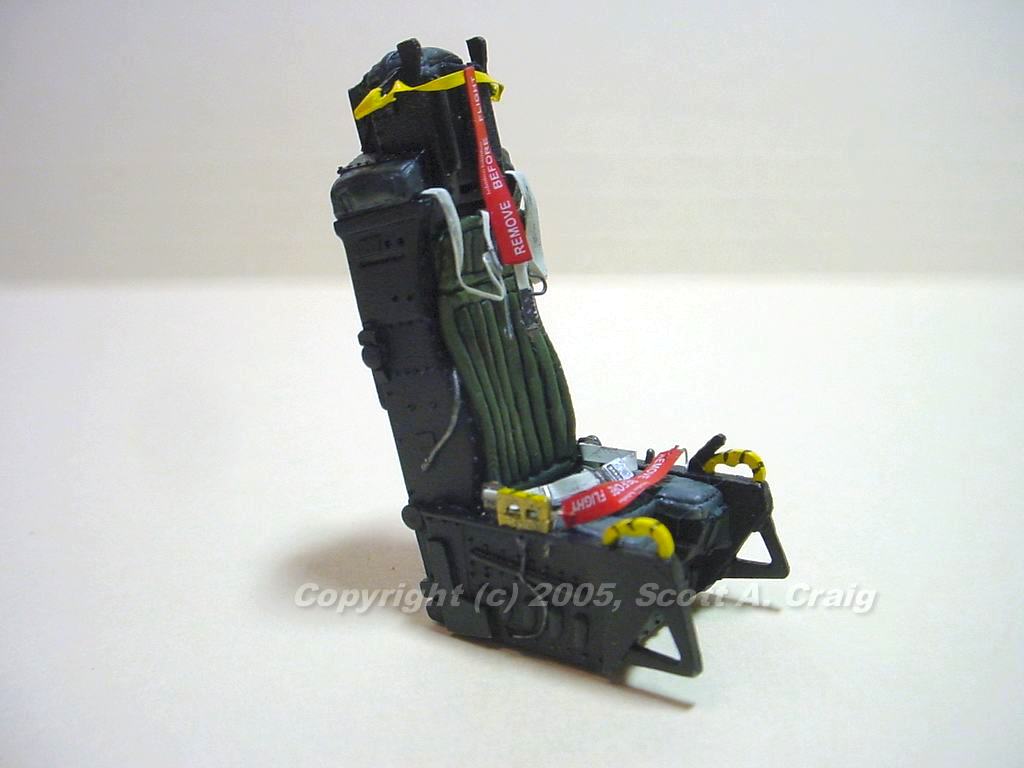
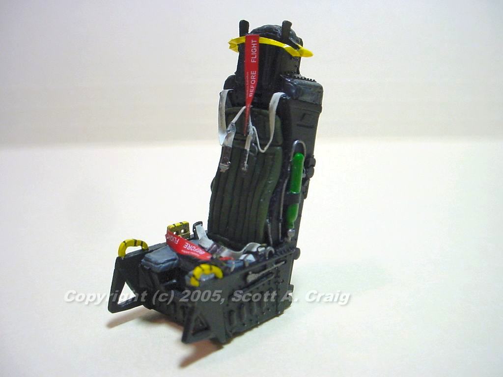
The instrument panels are
Eduard color photoetch, the ejection seat is
Cutting Edge resin with
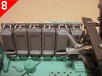
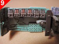
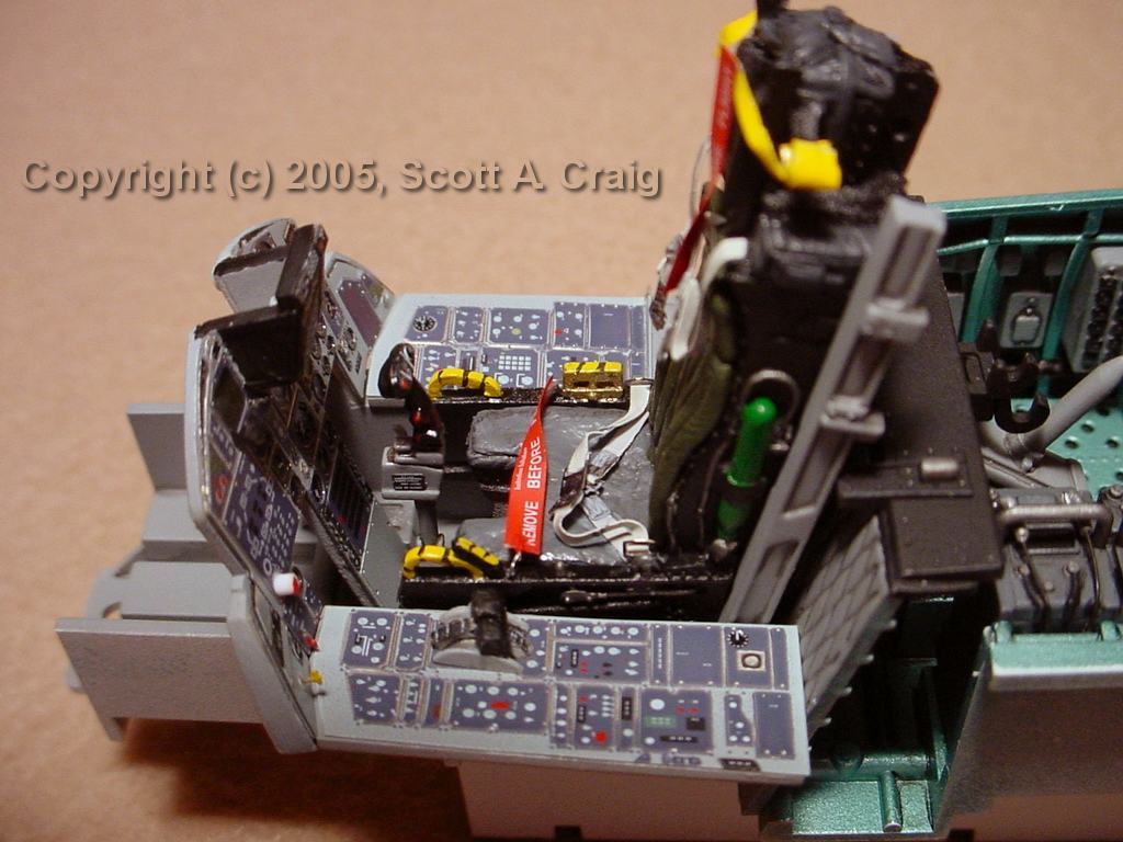
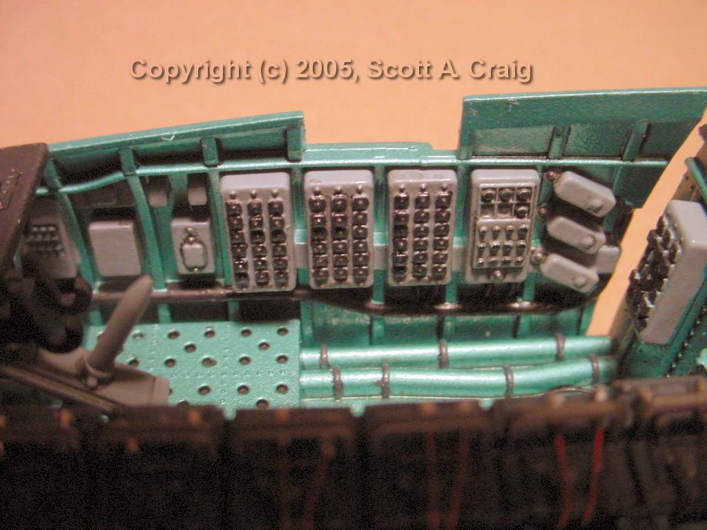
Eduard PE belts and harnesses. The electronics bay behind the cockpit is painted
with Xtracolor X159 "F-15 Avionics Bay Metallic Green/Blue" from
Roll Models (note that this paint is oil based
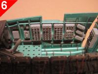
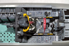
and takes several days to dry). The wiring on top of the TEWS units (photos 8
and 9) was scratch built. Short pieces of solder were drilled out to simulate the
connector to the unit, a piece of thin wire pushed through the solder and into a hole
drilled into the TEWS unit. The wires were then painted orange and black to match
reference photos of the area. The Remove Before Flight flags are
Eduard Color PE (note that they are 1/48 scale flags and not 1/32 scale). The
yellow harness that goes between the pitot tubes on the ACES II ejection seat was scratch
built from foil.
October 20, 2005 -- I haven't done much on this
model in the past month or so. I haven't really put it on hold, I'm just focusing more
of my time on the Trumpeter
F-105D that I am building for a friend. Also, the
Afterburners
are giving me a fit and I haven't decided how to fix them yet.
|
|
Note that I have not been following the instructions exactly in order so these notes
are not in any particular order. I added them to this page as I finished a section
or noticed something that needed to be added to the page.
|
GENERAL ......
|
| |
Many interior areas of the F-15's may be painted in a blue / green metallic
color. Probably the most common place that modelers will run across this color is in
the electronics bay (Bay 5) right behind the cockpit on F-15A and -C models. According
to what I have been able to determine, this color was discontinued between 1979 and
1980. Also, many aircraft that have had depot-level maintenance performed on them since
1980 have had the bays repainted in gloss white. This is not always the case though
because I have read that aircraft stationed at some bases, Kadena AFB for example, did not
have the bays repainted. Keep in mind that this information is based on what I have been
able to find on the internet and may be incorrect. If anyone has any additional comments
or information, I would greatly appreciate
An Email about it.
Update - 01/09/2007 - Thanks to Donivan and his contacts at the USAF for verifying that
Bay 5 is now being upgraded to gloss white during depot-level maintenance.
Here Is An Example of
what the color looks like. The photograph was provided by Dave Masters and has been used
here with his permission.
There are ways to mix this color, but the only exact match that I have been able to find is
Xtracolor X159 "F-15 Avionics Bay Metallic Green/Blue". I have heard that there
are also Gunze-Sangyo and Polly Scale matches but I do not know what they are. I
ordered the Xtracolor paint from Roll Models and
their item number was XT159. I read somewhere that Xtracolor paints are oil based,
and I can believe it because it takes a good while to dry (as in 36-48 hours). To my
eye the Xtracolor X159 paint is a very close match to the actual color and may be seen in
the Construction Photos section above.
|
COCKPIT ......
|
| |
Photos of the completed cockpit and electronics bay can be viewed in the
Construction Photos section above.
I'm using a color photoetch interior for the first time on this model. It is the
Eduard 32532 set The main instrument panel consists of two layers of PE to give
the instruments some depth but the side panels are only a single layer of PE. The
detail that Eduard printed on the panels is excellent and really enhances the cockpit.
One thing I dislike about the main panel are the two screens at the top of the instrument
panel. Both of those screens are printed in a somewhat medium green color with light
green lines shown on them. For an aircraft in flight this would be fine, but for a
parked aircraft the avionics would be off and the screens would be dark green with no
lines showing on them. This is not a big issue since all that is necessary is to
paint over the screens with some relatively dark green paint.
Also take note of the fact that the Eduard color PE panel is a "Pre-MSIP" (Multi-Stage
Improvement Program) panel. The MSIP replaced most of the avionics and weapons systems
in the F-15 with vastly updated systems. Keep in mind that many of the F-15's have been
in service for over 20 years and there have been quantum leaps in electronics over the
intervening two decades. According to
This Page on the Robbins AFB web site, "All F-15A/B/C/D aircraft produced before 84-001
will receive the MSIP retrofit at the F-15 depot. This upgrade added a MPCD
(Multi-Purpose Color Display) to the weapons panel on the left side of the main
instrument panel which is not on the Eduard panel. In addition, the MSIP upgrade gave
the F-15 the ability to carry AMRAAM and did not have the LAU-128 launch rails, so any
Pre-MSIP aircraft could not carry AIM-120's. Also, they did not have the round
antenna on the right tail cone, so be sure to use the pointed one that Tamiya provides. Thanks
to my buddy Darren for this information.
For photographs of the completed main instrument panel see the
Construction Photos above.
If you decide to use the
Eduard 32532 Interior Set there is one minor detail that you will need to be aware
of. There are three panels that replace the main instrument panel and both side
panels. You will have to sand the existing instruments off of the kit panels, but
this is a minor chore and only takes a few minutes.
The problem is that the left side panel requires that you cut the throttle quadrant off
and reuse it. Since the throttles are on the side of the panel closest to the seat
it makes it difficult to cut them out without the gap showing in the edge of the panel. It
is probably possible to score around the throttles with a hobby knife and leave the edge
of the kit panel in place, but there is not much room. I just used a saw to cut the
throttles out. This did leave a gap in the edge of the panel, but the panel at that
area is 0.040" thick so I used two pieces of 0.020" styrene (because I had some on hand)
to fill the edge back in. It only took a few minutes to do.
If you decide to use the
Eduard 32056 PE Set - F-15C Exterior Detail Set it does include some pieces for the cockpit,
specifically belts and harnesses. One piece that the instructions indicate should be
installed is incorrect. The very first section indicates that a center ejection
pull handle (part no. 13) should be installed on the ejection seat. While this is
correct for the ACES II in an F-16 it is NOT correct for the F-15 seat.
Here Is A Link to the ACES II seat of an F-15 on
The Ejection Site and Here Is A Link
to an ACES II of an F-16 on the same site. Notice that while the F-16 seat does have
the center pull the F-15 seat does not. The description of the seat on the F-16 page
specifically mentions that the seat for the F-16 and F-22 differ from other variants in that
they use a center pull. If you see a photo of an F-15 with a center-pull ejection seat
it is an older style Escapac ejection seat.
If you decide to use the
Cutting Edge Ejection Seat be aware that it does not have seat rails
on it. The kit rails are molded to the seats, but they are not difficult to
cut off and add to the resin seats.
Additionally, there are two brackets on the bottom of the Tamiya seat that you will need to
use. Without it the Cutting Edge seat will sit too low. There are two pieces,
one on each side of the seat that fit into slots in the cockpit floor. Just cut
them off the kit seat, make sure they are the same height, and glue them into the cockpit
floor using the slots provided. When you are ready to install the Cutting Edge seat
just glue it to the tops of the brackets.
Even though the F-15C is a single-seater Tamiya provides two ejection seats. I guess
it's easier for them to have one parts bag that works on the F-15C and F-15E even though
there is an extra seat for the "C".
If you decide to use the
Eduard 32532 Interior Set the instructions show part number 17 (lower left of page 2)
in the wrong location. This part appears to be three placards connected as a single
unit. The instructions show it mounted to the edge of the cockpit beneath the
windscreen. As can be seen in
This Photograph they are plainly visible (well, two of them are "Plainly" visible,
the third is not as easily seen) right in front of the rear edge of the windscreen
ABOVE the rim of the cockpit on the framing of the windscreen.
|
ELECTRONICS BAY ......
|
| |
Photos of the completed cockpit and electronics bay can be viewed in the
Construction Photos section above.
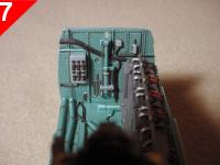
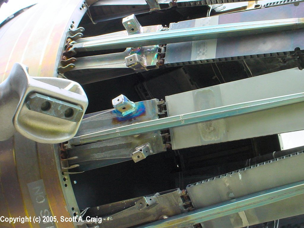
The electronics bay immediately behind the cockpit is "Bay 5". In the middle of the
bay floor there is a large round stud sticking up that a screw goes through to join this
part with the nose gear bay below. There is nothing to cover this stud except the
screw head itself. There is nothing similar to this in the real bay and it would
probably be best to grind it out and putty the hole. The problem with this is that
there are some cables and cable trays that pass through it that would have to be
reproduced. I chose to leave it and filled the screw head (it is a small Phillips
screw) with gap filling Zap and then painted it the same color as the bay.
The Electronics Bay is frequently painted in the metallic blue / green color as mentioned
in This Comment shown above. If the aircraft was manufactured
after 1979 or has been upgraded the bay might have been painted gloss white.
|
ENGINES ......
|
| |
I decided to use the
Cutting Edge exhaust nozzles instead of the kit parts. According to the information
provided, the Tamiya nozzles are approximately 1/4" longer than they should be. Photos
of the completed cans can be seen in the Construction Photos above.
Based on the photographs I have found on the internet the exhausts of the F-15 range in
color from a dark metallic "Burnt Iron" color to a bright "Stainless Steel" color. I
suspect this has something to do with the age of the engines and how they have been treated,
but the bottom line is that it appears pretty much any color would be correct in some
respect. I used Alclad Stainless Steel for mine and then gave them a black acrylic wash.
Also, the insides of the augmenters (or "Cans") on the engines are ceramic coated so they
are white in many places. As would be expected there are numerous areas of black soot,
but the background is white or a very light ash gray, not metallic.
Finally, of all the photos I have looked at that show the "Turkey Featherless" exhausts
of the F-15, none of them show any heat discoloration. I took some photographs of
an F-15A with early engines that have "Turkey Feathers" and they show distinct
discoloration from heat. That can be seen in
This Photograph. However, as can be seen in the exhaust photographs on
This Page taken
by Zoltan Pocza there is no evidence of heat discoloration.
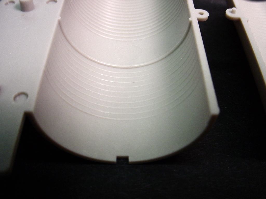
The intake trunks and afterburner sections are tough. That isn't unusual on jet
models though. As usual both of these consist of an upper and lower half that are
glued together to form the intakes and burners.
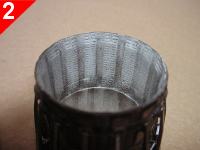
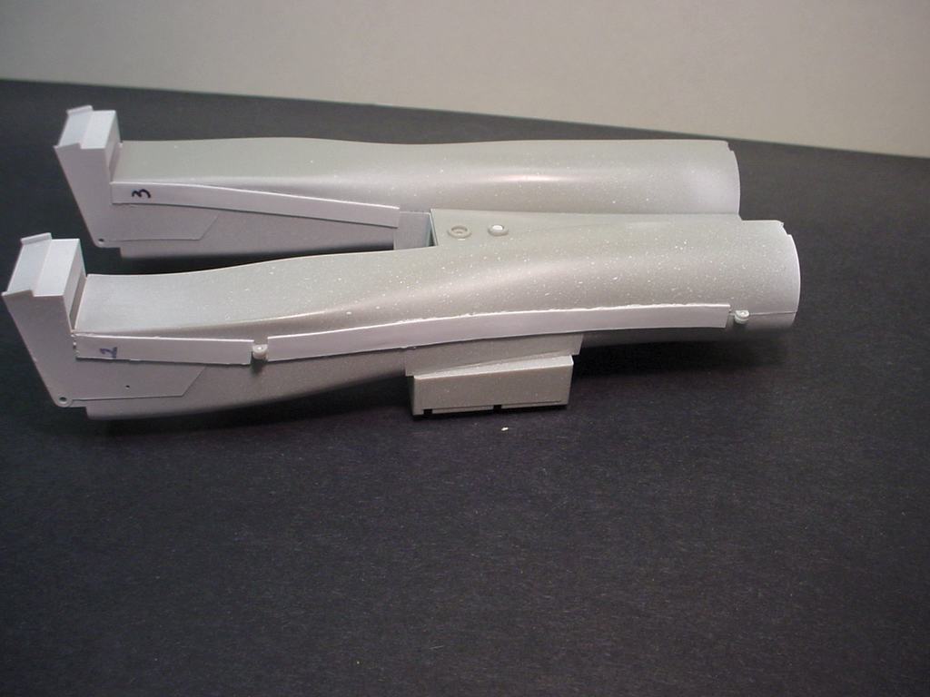
The intake trunks just take some patience as can be seen in the photos below. All of
the images are links to larger photographs. Click the image to view the larger photo.
Photo 1 shows the left intake after being glued with Tenax and a coat of Mr. Surfacer 1000
applied. You can easily see the seam starting at the
upper corner, angling down, and then going all the way to the back end. Photo 2 shows
the right side of the assembly after the seam was removed. Before filling and sanding
it looked the same as the mess on the left side. It took several hours of filling,
sanding, and priming to see if the seam was gone, and then repeating the process until it
actually was. It takes some work but here is the proof that the guys who say it can't
be done are dead wrong.
Photo 3 shows the outside of the intake trunks. You can see some strips of styrene
down the sides that aren't included in the kit. I normally put those on the outside
because after putting a lot of work into getting seams out I really don't want the joint
to split back open. I sometimes have to sand them down in places to fit into the
fuselage but the really do help strengthen that joint.
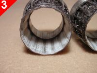
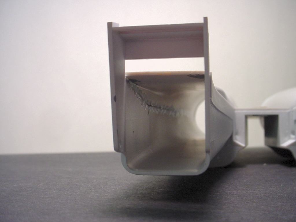
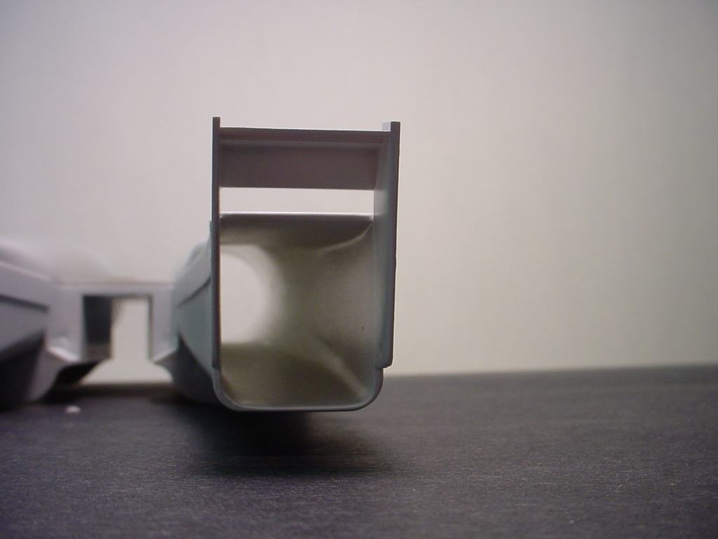
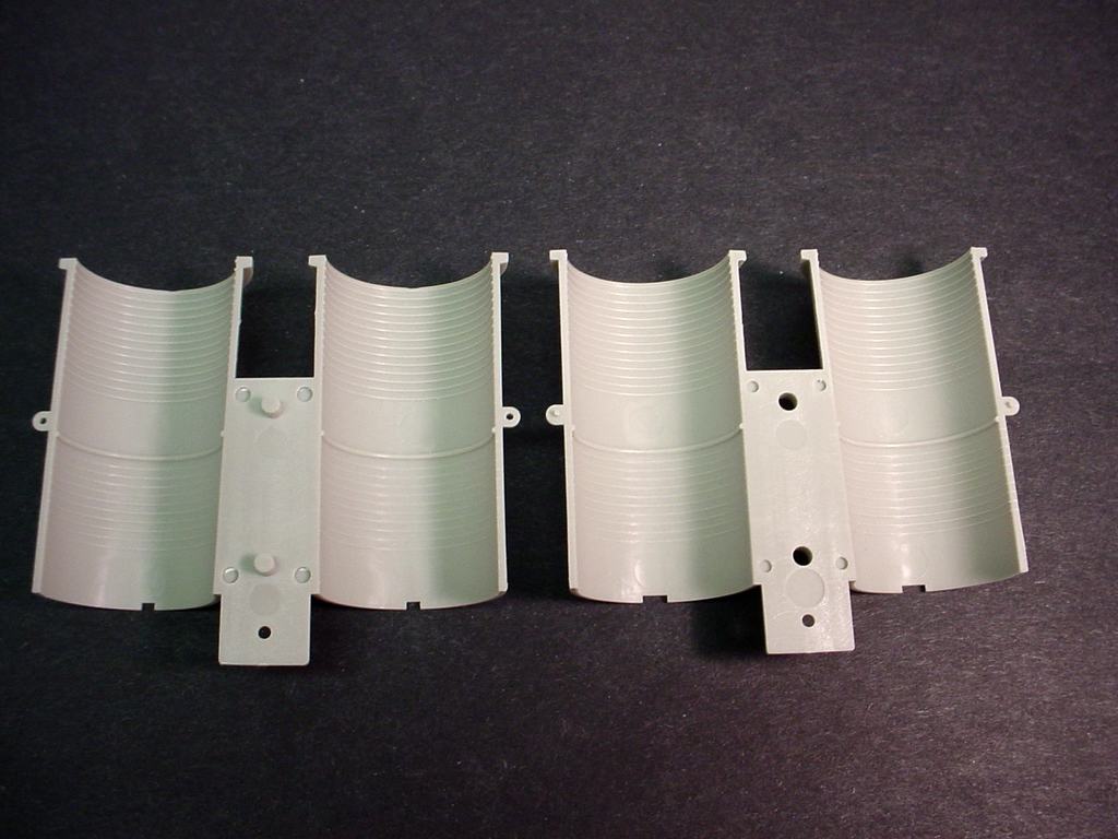
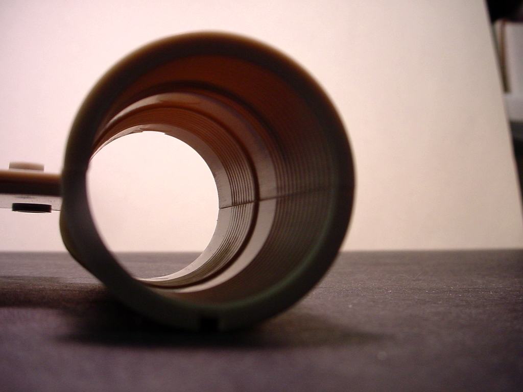
The afterburner sections are just plain evil and I haven't done them yet. Photos of
the parts are shown below.
As can be seen in photos 4 and 5 the inside of the afterburners is ribbed. Photo
6 shows the seam that is going to be present when the two halves are assembled. Any
sanding that is done to remove the seam is going to ruin the ribs. Even using a
"Welding" type of glue such as Tenax that creates a bead of melted plastic is going to be
difficult to fix. I've gotten some good advice on how to resolve the problem and
when I get them assembled I'll post some photos here and information on how I did it.
|
ORDNANCE ......
|
| |
I haven't done a lot on the ordnance yet. I got tired of working on other things
and decided to play with the missiles just for a change of pace.
AIM-9L -- The Sidewinders are in pretty decent shape (compared to those in some
other models I could mention they are in great shape!). Each missile is composed of
5 parts; the main missile body with two forward and aft fins molded on, a single piece that
forms the other two aft fins, two individual forward fins, and an end cap. There are
four ejection pin marks on the top (I think it's the top) of the main missile body. These
pin marks may or may not be visible once the missiles are mounted. I don't think they
will be but I decided to fill them anyway. There are also some minor seams along the
sides where the mold halves joined, but these are easily sanded off. The end cap has
a minor ejector pin mark in it that needs to be removed.
I found an excellent source on the internet for AIM-9 information. The site is
Jim Ball's Scale
Library of Missile Data and his page pertaining to the AIM-9 is at
This Link
Most of the photos appear to be of an AIM-9D but they still provide some excellent
reference for the modeler.
AIM-7 -- I haven't even touched the Sparrows yet so I don't know how they will stack up.
|
|
For anyone who might be interested, here is how my time breaks down so far. Keep in mind that I don't
punch a time clock or anything like that. After I work on it a while I write down approximately how
much time I spent on it and what I did. It's relatively close, but not exact by any means.
| General Assembly |
29.5 hr |
|
5% Complete |
| Painting (excluding cockpit, engines, stores, & landing gear) |
14.0 hr |
|
2% Complete |
| Decals and Panel Line Wash |
0.0 hr |
|
0% Complete |
| Engine Exhausts (including painting) |
17.0 hr |
|
85% Complete |
| Intake Trunks (including painting) |
17.5 hr |
|
100% Complete |
| Cockpit & Electronics Bay (including painting) |
51.5 hr |
|
100% Complete |
| Stores (including painting) |
0.0 hr |
|
0% Complete |
| Landing Gear (including painting) |
10.0 hr |
|
33% Complete |
| TOTAL TIME THROUGH 09/15/05 |
139.5 hr |
|
15% Complete |
|
| Aircraft Name: |
McDonnell-Douglas F-15C-23-MC Eagle |
| Year of Construction: | 1978 |
| Aircraft Category: | Air Superiority Fighter |
| Wing Span: | 42.8' |
| Overall Length: | 63.8' |
| Height: | 18.5' |
| Gross Weight: | 44,500 lbs |
| Engine: | Two F100-PW-220 Pratt and Whitney turbofan engines with afterburning |
| Thrust: | 14,670 (dry) / 23,830 (afterburning) pounds each |
| Speed: | Mach 2.5 |
| Range: | 3,450 mi (ferry range with internal fuel, 2 FAST pack conformal fuel tanks, and 3 external drop tanks) |
| Ceiling: | 65,000 ft |
| Date of First Flight: | July 27, 1972 |
| Date Deployed: | November, 1974 |
| REFERENCES AND MY THANKS TO ... |
|
