|
|
| CONSTRUCTION NOTES: |
If you have specific questions about the kit in general or any of the aftermarket parts I used on it, please
feel free to send me An Email and I'll be glad to answer any questions that I can.
|
| 1 |
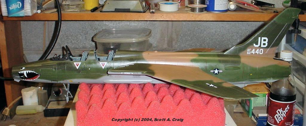
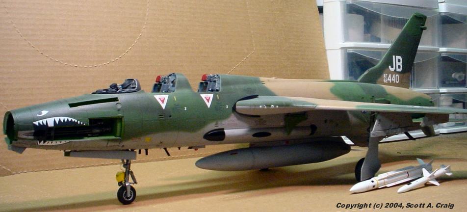
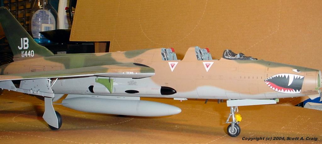
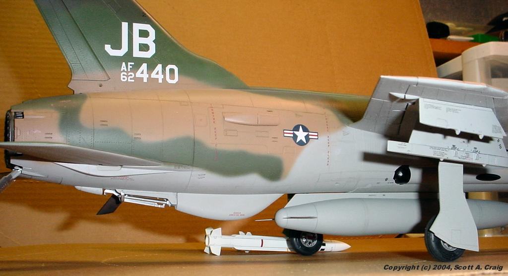
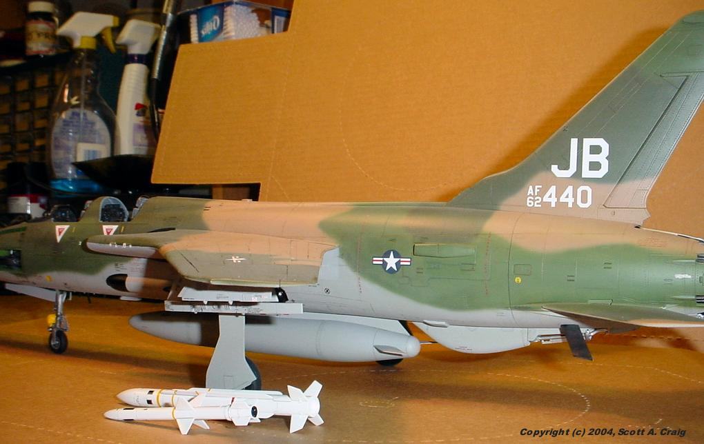
The decals for tail number 62-4440 show a tail code of "JB" whereas most of the photographs of 62-4440 show
a tail code of "WW". "JB" is the code for the 17th Wild Weasel squadron of the 388 Tactical Fighter Wing,
USAF. "WW" is the tail code for the 561 Wild Weasel squadron of the 388 Tactical Fighter Wing, USAF.
The kit documentation indicates that the model of 62-4440 is of 17 WWS, 388 TFW, and the information on
This Web Site indicates
that 62-4440 was never assigned to 561 WWS, 388 TFW.
I cannot explain why the photos of 62-4440 indicate that it was with the 561 WWS / 388 TFW however it obviously was
at some point. If you want your model to be correct with the photos, use the "WW" tail code from 38-320 instead
of the "JB" decal. I think that would be more correct since all the photos I have found of 62-4440 indicate that
it was with 561 / 388.
Later ... I was looking at some info on the internet somewhere and read that the "WW" shown on 62-4440 was placed on
it to indicate that it was a "Wild Weasel". Apparently the "WW" has nothing to do with 561 WWS / 388 TFW and
was just put there after the aircraft left active service. Some of the pictures I have seen of 62-4440 show it
in an old and dilapidated condition, which does not agree with the "WW" being put there for the static display.
I do not remember where the site was that had the comment. I decided to go with "JB" on mine since it was the
proper squadron identification for the aircraft when it was stationed in Thailand with 17 WWS / 388 TFW in 1972.
Edit 08/07/05 -- I received an email from an instrument specialist who is familiar with this particular aircraft
and he said that the "WW" letters do indeed belong on this aircraft. To late for me to change mine though! Thanks, Phil.
|
|
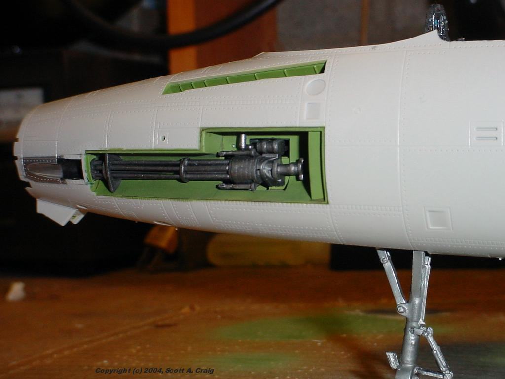
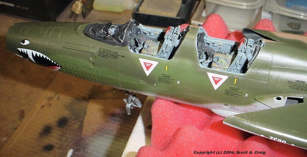
| 2 |
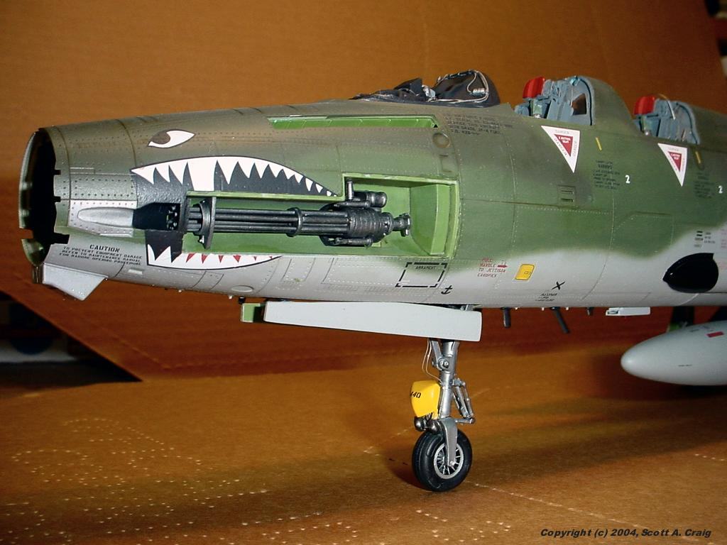
The muzzle of the M-61 Vulcan cannon has a couple of problems. First, the muzzles are solid and are not
drilled out. Since they will probably be somewhat visible through the gun port I'd recommend you take
10 minutes to drill them out slightly.
Second, the muzzle part has all six muzzles molded onto a ring. The back has 6 dimples into which the
ends of the barrels are to be glued. If you look you will see that the dimples on the back are in
between the muzzles on the front. In other words, if you glue the ends of the barrels into the
dimples they will be 30 degrees out of alignment with the muzzles. I'd recommend that you fill the
dimples on the back with putty, CAREFULLY and lightly sand the ends of the barrels so that you have a nice,
flat surface and then glue the muzzle part on so that it is properly aligned with the barrels.
Admittedly it won't be readdily visible, but this is another 5-minute fix that improves the accuracy of
your model.
|
|
| 3 |
The engine's afterburner section has four pieces that have to be glued together to form a cylinder. You
can imagine how prone to error that is! All four of the pieces (E-11 through E-14) glue around the afterburner
vanes (part E-2 I think) so the easiest way I found to align everything is to tape them together around part E-2.
Tape part E-13 to E-2 by running a piece of tape over the end of E-13 into E-2. Hold the next section in
place, and tape it tightly to part E-13. Then the next one and then the fourth one. Once all four are
in place, align them properly and glue them where they join part E-2, then glue the joints together.
Those four pieces are also liberally scattered with ejector pin marks. If I remember right there were about
six on each piece and every one of them are in between ribs that make it very difficult to remove them. You
can leave them if desired, but anyone looking in the tailpipe will be able to see them.
I painted the inside of mine with Citadel "Boltgun Metal" then overcoated that with Tamiya Smoke sprayed only from
the front ends of the parts. That left a slight metallic sheen where the ribs are. Finally I sprayed
a mist of flat black, making it heaviest at the rear, also spraying only from the front to simulate flow through
the engine, and finally applied a matte finish (I use Tamiya Flat Base mixed with Future).
I didn't do much detailing at all on the outside of the engine since it will be enclosed in the fuselage.
If you are in to scratchbuilding it is a beautifully detailed subsection and would look great on a scratchbuilt
engine stand or cart. I did add a couple of baffles inside the fuselage so that anyone looking in the
intakes wouldn't be able to see all the way to the rudder!
|
|
| 4 |
The decal instructions are not that great. There are a lot more decals than are shown on the instructions.
Look at the instructions closely!
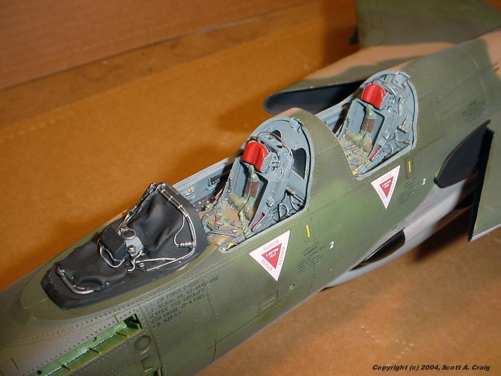
Also, there are a couple of decals that ARE shown on the instructions that are not on the sheet. These are the ones that go
over the canopy latches. There are two shown on each side of the aircraft so that you need four, but the decal sheet
only has two total.
This holds true for the missiles as well (I didn't assemble any of the bombs or other ordnance so I'm not sure about
them). The instructions indicate a decal on both sides of the AGM-45 Shrike missile, however there are only
enough decals to put one on each if you assemble all five missiles.
Another note about the Shrike: There is a red stripe decal that goes between the fins. You will need to cut that
decal into four equal parts to get it to work. Measure carefully because there is only about 1/32" extra on
each quarter of the stripe.
The decals were made by TwoBobs Aviation Graphics and as would be expected from
Bob Sanchez they are fabulous. Put a little decal solution over them and they will look painted on. You
should also be very careful with them since they tear easily. This is simply a fact of thin decals, and Bob
makes them very thin indeed.
|
|
| 5 |
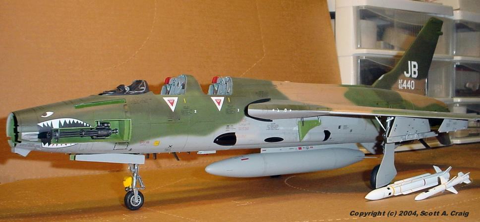
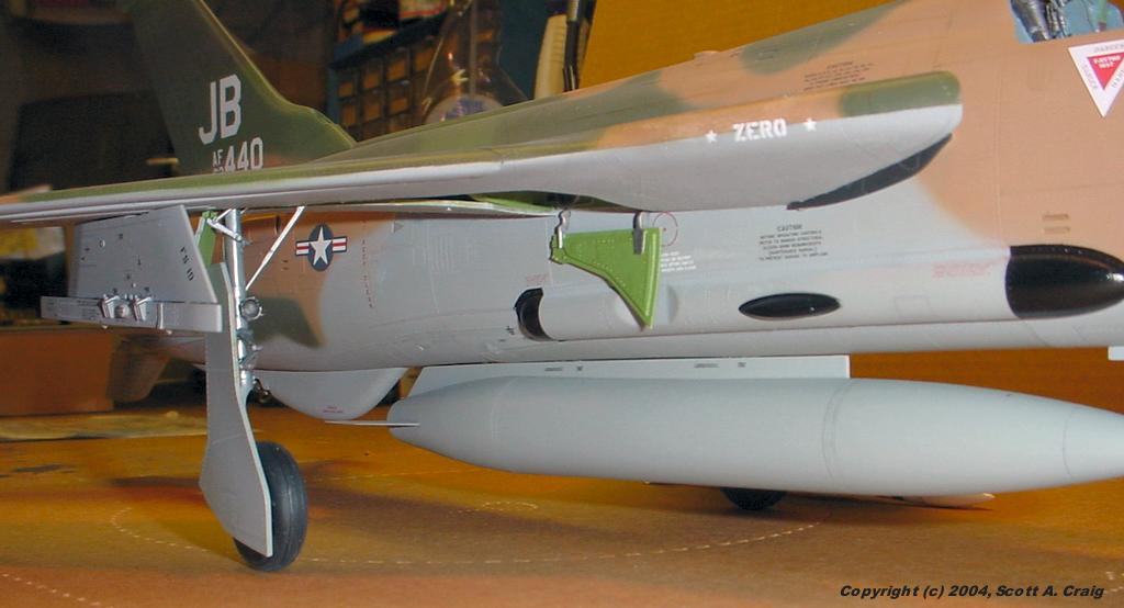
The AGM-45 Shrike missiles are closed on the end. Real missiles are not. I drilled a hole in the back
of mine, and then took a small round file and opened the back end up. I then put a plug of Milliput down in
the hole about 1/4". It looks much better than having a closed up end. The AGM-78's are the same way,
however from the photos of real ones that I have seen they are plugged just below the end of the missile.
|
|
| 6 |
There is a hole in the leading edge of the rudder. From the picture I have found this appears to be some sort
of vent or intake. Save yourself some trouble and paint the inside of the rudder around that hole as well as
the top of the fuselage before you assemble and install the rudder. For some reason I though there was something
that went over it, so I didn't paint it. It is not easy to get in there with a MicroBrush and paint it after
everything is assembled!
Edit 08/07/05 -- I was informed by a friend who flew F-105's for many years that this vent, as well as the two
on the sides of the fuselage, were a modification added to ventilate the engine compartment to prevent fuel and
vapor from building up it. As you can imagine, fuel and vapor buildup there could be a lethal
problem! Thanks Joe!
|
|
| 7 |
John McCormick has also built this model and has written an excellent review of the construction. You can
see his review, along with plenty of photographs, at
This Link on the LargeScalePlanes web site.
|
|
|