COCKPIT ......
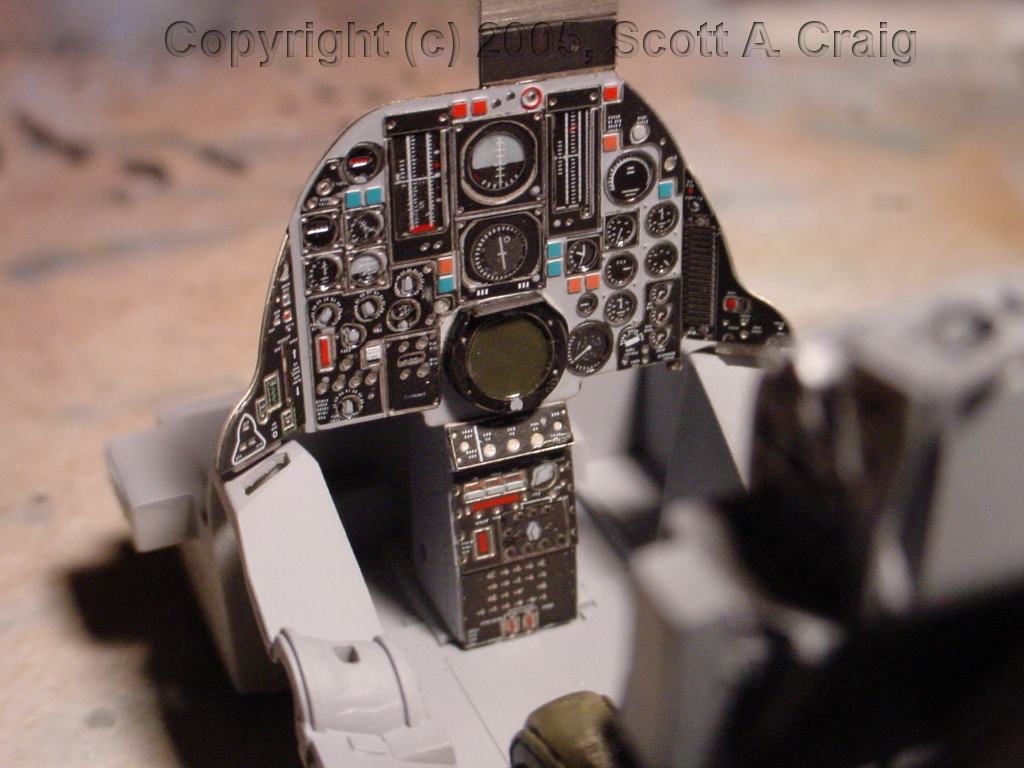
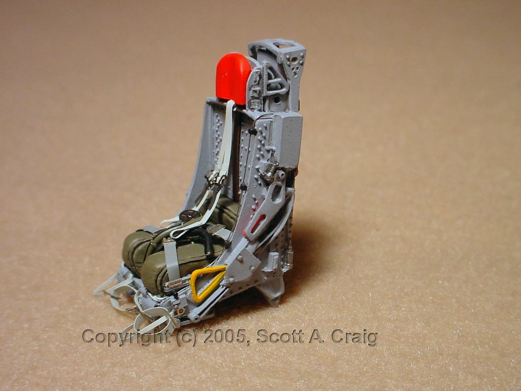
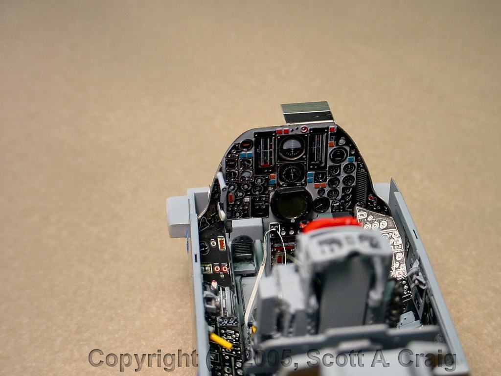
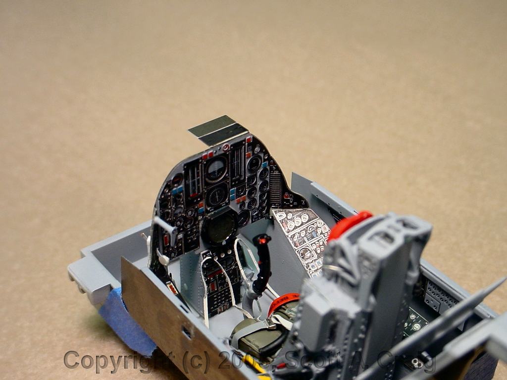
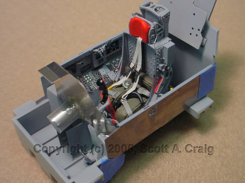
09/24/2005 -- Here are a couple of photos of what has been done so far. Nothing
major has been constructed, but the main panel is done and the seat partially done. I
am using Eduard color photo etch for the cockpit as well as a cast resin ejection
seat. The seat will be dressed up with some tubing and wire to make it look more
realistic, and it will also get a coat of clear flat. It is still glossy right now
because I still have some work to do. The belts and harnesses are photo etch as well
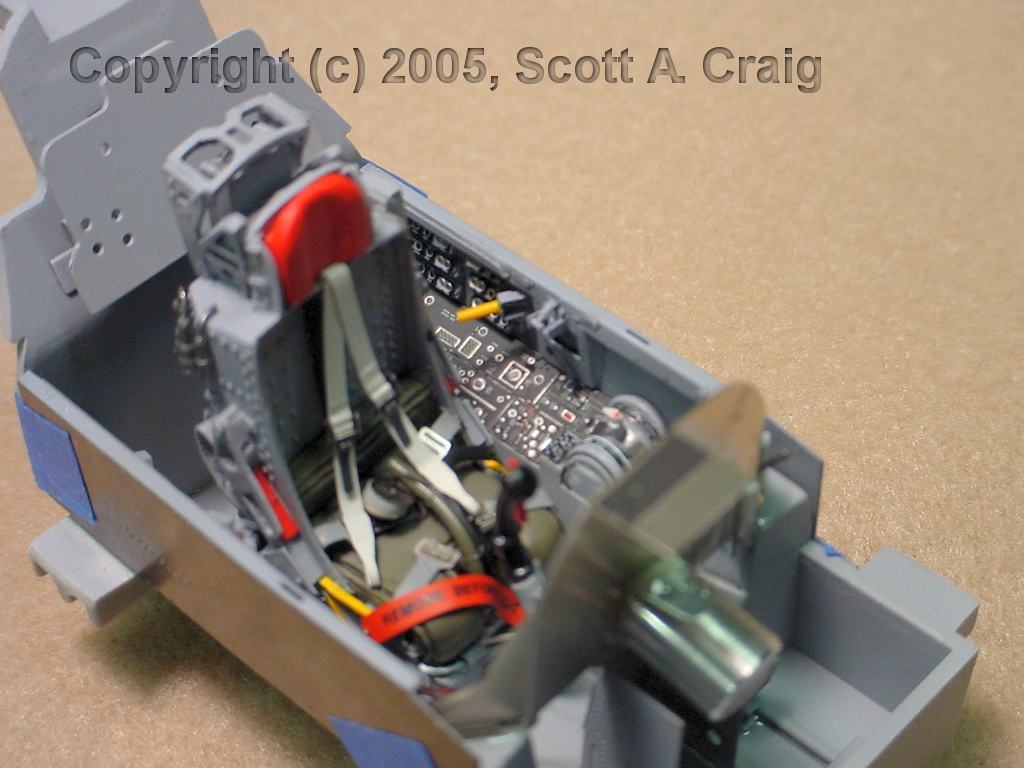
and have not been added yet. Also note that nothing has been glued into the cockpit
yet. The panel and seat are just sitting in there for the photos which is why they
aren't sitting flush as they should. The panel sides fit into some slots in the
cockpit and will be flush when everything is done. Finally the tab on top
of the main panel is for the SAM warning gear. I'm not sure at this point whether
it will stay or not. I'm using parts from two resin sets and two PE sets on the
cockpit. It makes it kind of difficult to know what to use, what to ignore, what
to leave, and what to cut off.
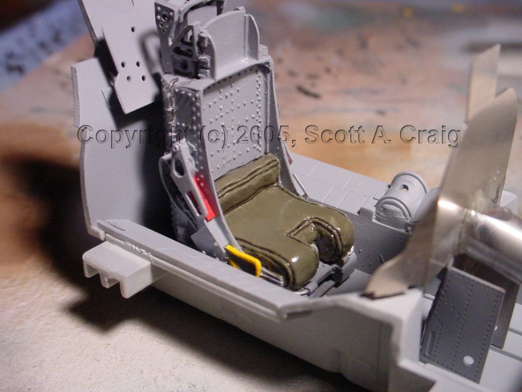
There is an area above the red arm rest on the right side of the seat that looks like
red paint has gotten onto the gray frame of the seat. There are also some minor
areas around the yellow ejection handle that look the same way. Those are
reflections of the color on the gray seat frame. Everything is still glossy and
causing the reflections. It will go away when I get the seat flat coated.
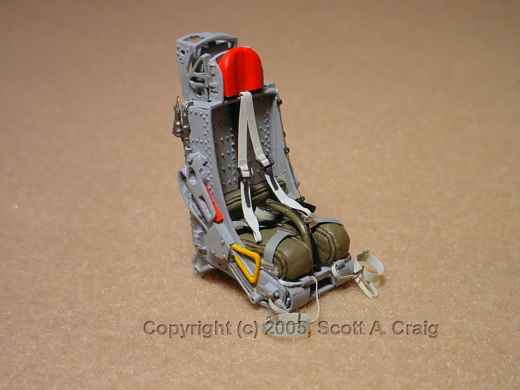
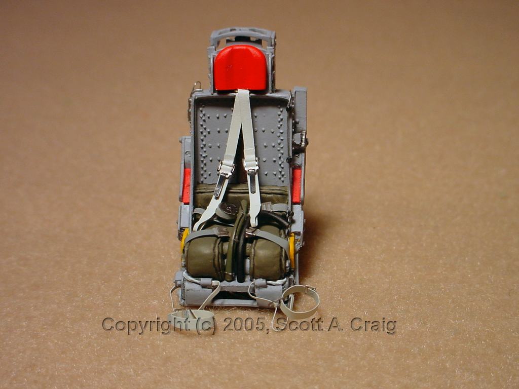
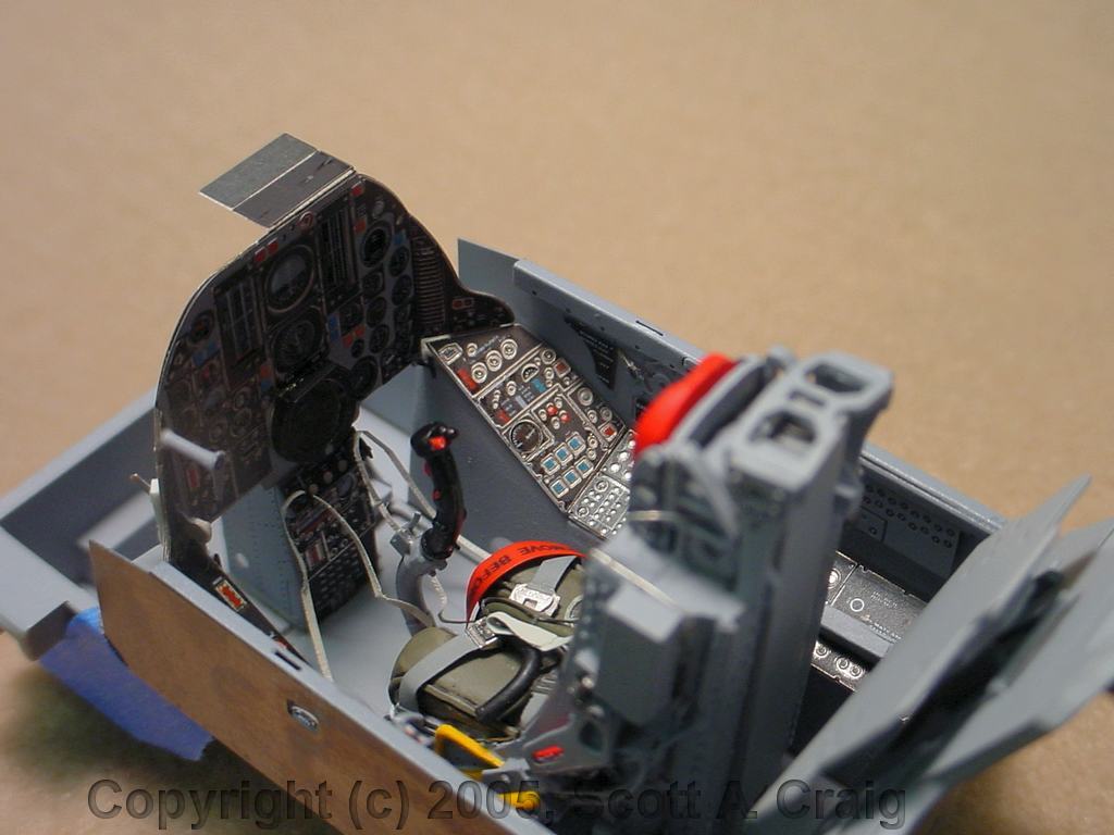
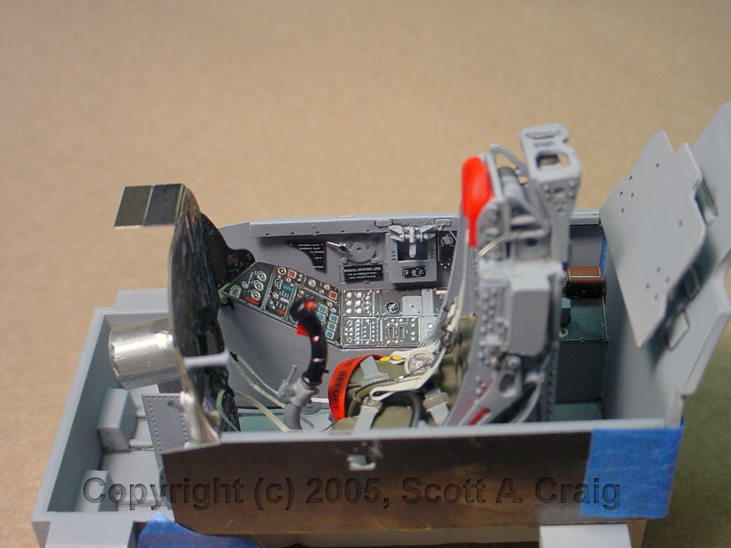
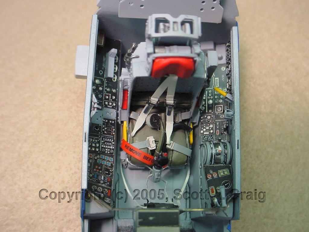
10/17/2005 -- At the request of the owner I've made a couple of changes to the seat. The
tube along the edge of the seat has been revised so that it is right against the seat. The
garters have also been removed from the leg restraints. According to him they were kept
in their lockers with the other flight gear. When they got to the airplane they connected
the garters to the leg restraints. I also added a seat safety pin on the right side of the
seat with a "Remove Before Flight" streamer.
- The side panels are not glued in place. I will have to finalize the position of
them when the cockpit is installed in the fuselage, so right now they are just taped in
place.
- The ejection seat is not glued in place either. It will be permanently installed later and the leg restraints will be posed at that time. Right now they are just hung over the t-handles on the main panel and haven't been "Posed".
If I counted right, the cockpit consists of 118 pieces of styrene, resin, photoetch, foil, and
wire, so it did take some time to assemble. In addition to the
Legend Dimensions resin
ejection seat and parts of the
Eduard PE Seat the cockpit consists of the
Eduard Color PE Cockpit, the kit "Tub", and some wire and foil added for other details.
ENGINE ......
11/05/2005 -- One of the worst things about this model, and I remember it well from the
F-105G I built
last year, is the afterburner. The burner is a cylindrical section that is assembled
from four curved pieces. All four of the sections are liberally sprinkled with
ejection pin marks and other trash. To complicate matters even worse the four pieces
are ribbed so getting rid of the trash without ruining the ribs takes a good bit of
work. Once that is done you still have to assemble the four pieces and get rid of the
seams in the joints, not an easy task. I painted it once and wasn't happy with the
way it looked so I stripped it and repainted it. I'm still not completely happy
with the results but it's about as good as I can get it.
The remainder of the engine is pretty easy since virtually all of it will be invisible
once it is installed in the fuselage. The only things that really need to be
painted and detailed, other than the afterburner section, are the front and rear turbine
faces, the flame holder, and the exhaust nozzle. The engine is hollow and the front
turbine face is open but it will be visible through the intakes. I recommend that
you cut out a piece of sheet styrene, paint it flat black, and put it behind the front
turbine face to improve the appearance.
One other thing you can do that will help is to put a shield around the front face of
the engine. On both my F-105G and this model I constructed a cone-shaped piece
out of sheet styrene. It extends forward from the front of the engine to the rear
of the intakes. Anyone looking into the intakes won't be able to see the inside
of a plastic model that way and it looks much better.
Just for the record, when I look at a jet model one of the first things I do is look
into the intake(s) and exhaust(s) because, to me, these are the most difficult areas
of a jet to get right. They invariably contain lots of seams that are difficult
to remove, and making them look right makes the whole model look better.
AFTERMARKET RESIN ......
CUTTING EDGE CEC32154 FUSELAGE CORRECTION SET #1
This set contains, among other replacement parts, a repalcement ventral strake that goes
on the lower area of the fuselage, and it is a piece of cake to install. All that
is necessary is to cut off the old ventral strake and then slide the replacement resin
part into the slot that is left. When trimming the area of the fuselage for this
piece I'd recommend trimming it as smoothly as you can. The instructions say
to use a razor knife and score the existing strake tangent to the fuselage until it comes
off. This is probably the best and easiest way to do it, and only takes a couple of
minutes. It is important that the cut be smooth because the replacement strake is
thinner than the one on the kit. It fits the slot exactly but the cut edges of the
kit strake extend out past the resin strake and will be visible if they aren't cut smooth.
I notice in the photo that I still need to do a little sanding on that side of the strake
to. You can see a small line at the top of the strake (the bottom in the photo) where
the epoxy I used to glue it in place oozed out a little.
If you need a chuckle, take notice of what else the instructions recommend that you do
with the old strake! Since their instructions are copyrighted I won't include what
they said here, but if you want to know send me an
Email Message
All the white dust in the rivet holes and panel lines is sanding dust and will be
cleaned off thoroughly prior to painting. No point incleaning it off now since
I've still got some more sanding to do in places.
CUTTING EDGE CEC32150 CORRECTED FIN AND RUDDER
This is a complete replacement for the kit vertical stabilizer, engine cooling intake,
and rudder. The casting is excellent and aside from some minor dimples there were
no major flaws on mine that needed repairing. A couple of things I would recommend
though:
I also have concerns that adding these two big slabs of resin that far to the rear of
the main gear may move the center of gravity aft and make it a "Tail Sitter". Luckily
the Fuselage Correction Set #1 also includes a big resin radome that will offset a big
part of it. Additionally most of the centerline ordnance is in front of the main
gear, and since that is resin on this model that will help as well. The instructions,
Page 9, Section 16, incicate that 110 grams of weight (3.88 ounces) need to be added to the
nose. I added that, and have a big, heavy resin radome that I added a 1/2 ounce of
lead to so everything should be fine. I won't know for certain until I get everything
assembled and the model sitting on all three legs. There is some room left in the
nose for more weight, so it isn't a major problem as long as the radome is left until the end.
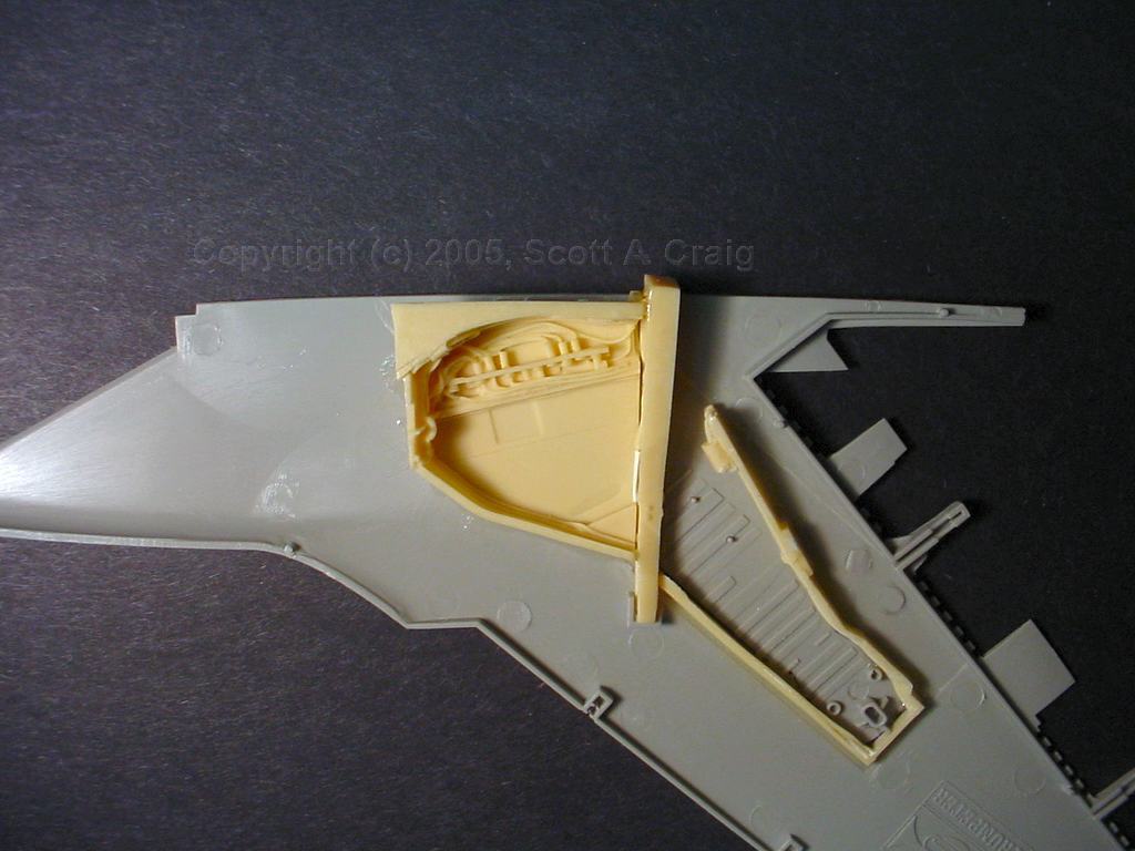
BLACK BOX WHEEL WELL UPDATE SET
While quite well molded and detailed the instructions for this set are absolutely
dismal. I got most of them done today (which took about 7 hours) and the best
advice I can offer is to work on one side at a time, use the other side for reference,
and be certain of what you are doing before you cut something. It would be very
easy to use a part on the wrong side or cut the wrong thing off because you cannot tell
ANYTHING from the instructions. The parts fit isn't bad, not great but not bad,
and the detail is much better than the kit parts. It is worth the effort but you
have to pay close attention to what you are doing.
Note that I installed all of the parts on the upper wing half whereas the kit had part of
them on the lower half. Since they have to fit together it's just a lot easier to
install them on the top half.
I still have some cleanup to do, you can see a slight gap between the wheel bay and the
bay wall that I need to fix, and perhaps some sanding when I get around to actually
fitting the wing halves together. I don't want to do too much until I get ready to
glue the wing halves together because I want them to touch the other wing half. I
also wanted to photograph the installation just as the parts go together. You may
notice some short sections of white styrene on the left side of the bay wall. There
are two molded wires there that prevented the wall from fitting properly because they
curved down and then back up right where the crossmember fits against the main section
of the bay. I sanded them off and replaced them with some short sections of
styrene rod of the same diameter.
There is also an obscure note on the instructions about cutting a 35mm slot on the intake
that is molded on the fuselage. This is because the wheel wells are larger than the
kit wheel wells, and also because while Trumpeter molded some of the wiring and the auxiliary
intakes on the sides of the fuselage while Black Box molded them into the wheel well. Be
aware that if you do cut this slot then the edges of the wheel wells will be visible to
anyone who looks down into the intakes. I spent a good bit of time grinding and sanding
both the wheel wells and the fuselage and did manage to get everything to fit without having
to slot the sides of the fuselage. I may have a minor seam to deal with where the bottom
of the wing joins the fuselage but to me this is preferable to having the wheel wells visible
through the intake. That would just be wrong.
The "Lateral Walls" as BlackBox calls them, the "U" shaped piece going to the lower right
in the photo above where the main gear struts would fold into, are VERY difficult to work
with. Someone at BlackBox thought it would be a good idea to mold both of them on
the same piece of resin, sort of interlocked together. Cutting them out without
breaking them is ROUGH (ask me how I know!), and once they are cut out the excess resin
has to be sanded off the bottoms without breaking them. I'd also recommend that you
temporarily put the two wing halves together and use a Sharpie to mark right against the
inside of the kit walls so that you will know how to line up the resin pieces.
When I started to fit the wing halves together to determine how much to grind off of the
fuselage to get everything to fit I also noticed that the height of the "Lateral Walls" did
not match the height of the inside of the wing. I wound up having to glue some
pieces of styrene sheet to the top of them (they are located on the lower left section of
the lateral wall in the photo above, but are not shown in the photo) and then sand it to
the proper height to eliminate the gap between the lateral wall and the bottom wing half.
Also notice in the photo above that the top of the "Lateral Wall" just sort of stops. It
doesn't connect to anything at all. After looking at some photos I decided that was
just wrong so I used a small piece of sheet styrene to close the area off.
The nose gear well isn't molded quite as cleanly and there was a good bit of overcast
among the tubes and hoses and wires that I had to clean off. It didn't take a lot
of work but did need some cleanup.
The gear doors included in the set are more detailed than the kit doors. The molding,
however, is not very clean in some places and somewhat difficult to clean up. Some
of them are also quite difficult to separate from the casting blocks so be careful and
take your time with them.
All in all this conversion set is a lot of trouble to install but if one takes their time
and is careful with their work it makes for a much more realistic model. Is it
worth the effort to install something that will seldom, if ever, be seen? I can't
answer that question for everyone, but it was for me.
Here is a photo of the installed ventral strake. The image to the left is a link to
a larger image. Click that thumbnail to view the larger photo. Notice that I
added a small piece of styrene on the aft and sanded it to match the profile of the
strake. The end of the ventral strake should be very close to the frame that holds
the arresting hook.
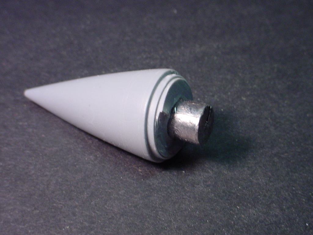
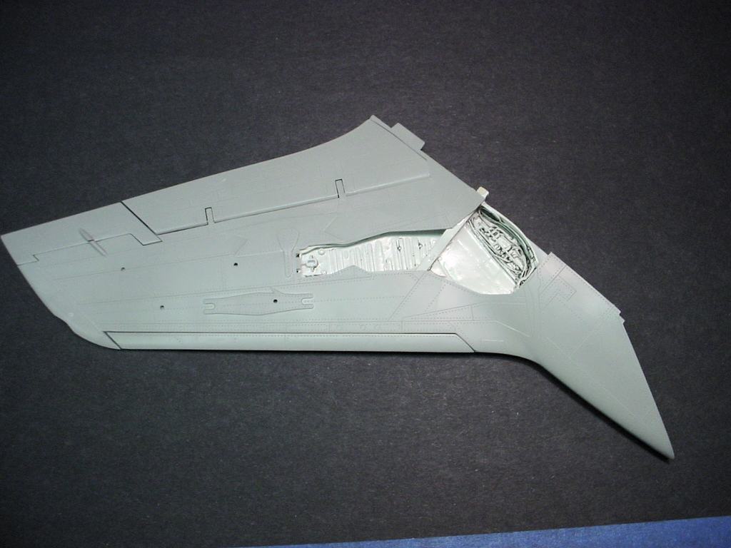
The kit also includes a replacement radome and RHAW antenna / strike camera. If
you follow the instructions the pieces go together quite well. You have to sand the
nose of the fuselage down about 1/8" (down to the first panel line).
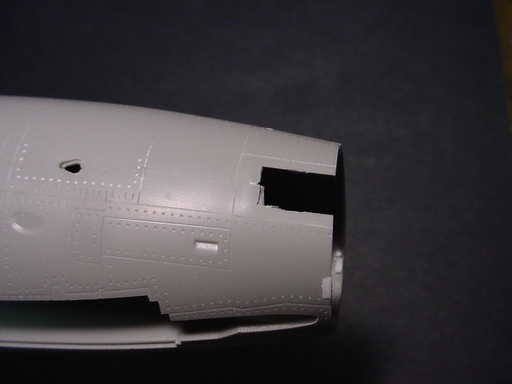
Here is a photo of the cut-down fuselage. The image to the left is a link to
a larger image. Click that thumbnail to view the larger photo. Notice that
after sanding you are left with three small notches that would hold the latches of the
factory nose cone. I used some 0.040 styrene to fill them in, and if you look closely
in the photo you can see that I let them extend inside slightly. The resin radome
fits slightly loose so I used these three pieces to tighten up the fit. It won't
matter at all once the radome is glued in place, but for fitting pieces I prefer to have
things fit somewhat tight. The radome is not glued in place at this time, it is only
stuck in the fuselage opening for the photograph.
The instructions have a note to add 100 grams (3.88 ounces) of weight in the nose. Since
the resin radome was solid it just seemed appropriate to drill a hole in the rear of it
and epoxy a 1/2" lead weight into it. I didn't try to get it all the way into the
radome, I just ground out a cone-snaped hole, stuffed it full of epoxy, and stuck the
weight in. I'll still need to add some more but since this was so far forward it
just made sense to add some weight there as well.
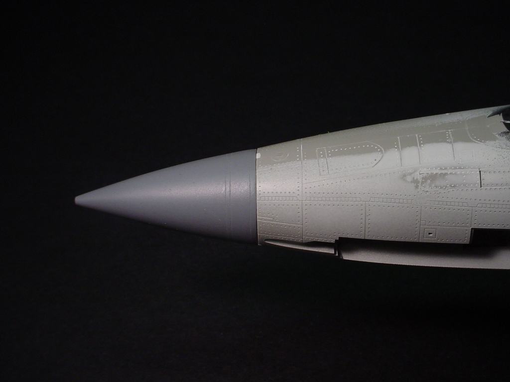
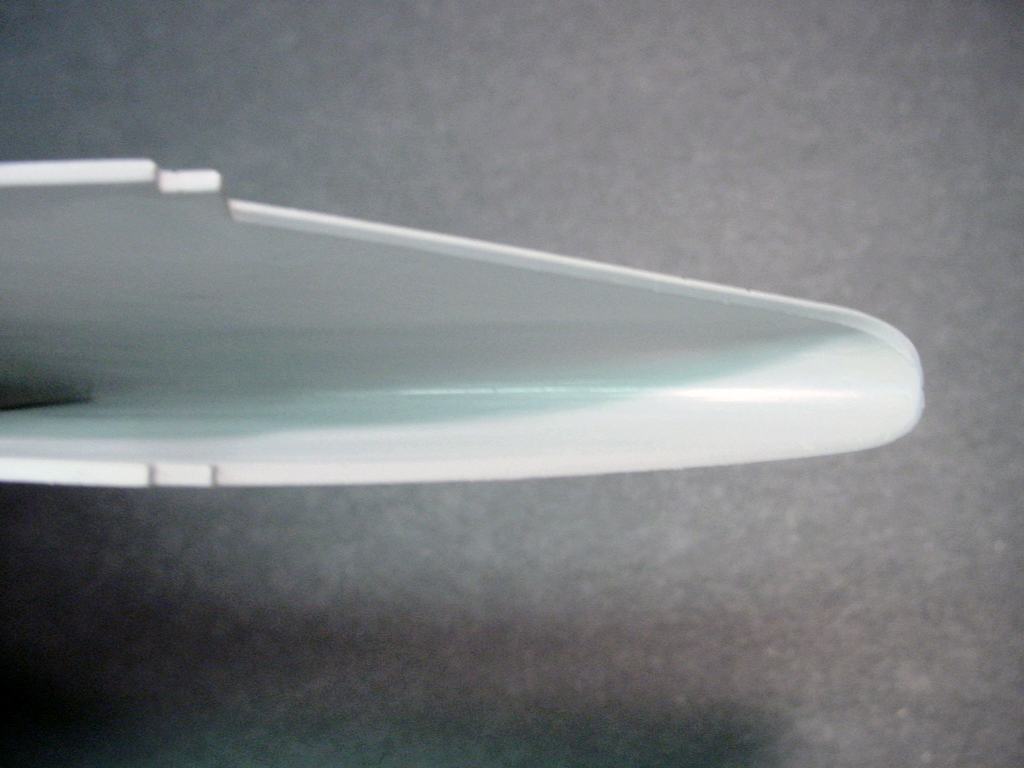
Here is the resin radome installed in the fuselage. It is not glued into place, just
stuck in the fuselage for the photograph. As can be seen it fits quite well.
The factory RHAW antenna / strike camera underneath the nose needs to be cut off. It
also needs to be cut off in such a way as to leave as much of the underlying plastic as
possible since the resin replacement isn't as wide as the factory one. I cut this
one off with a razor saw slightly above where it neets with the fuselage and then sanded
it down smooth. This leaves the thickness of the plastic in place. The inside
of the cut doesn't have to be smooth. Cutting Edge gives you a choice of an RHAW
antenna alone, a combination RHAW antena / strike camera, or neither. If you choose
the "Neither" option they include a resin plug to close up the hole that is left.
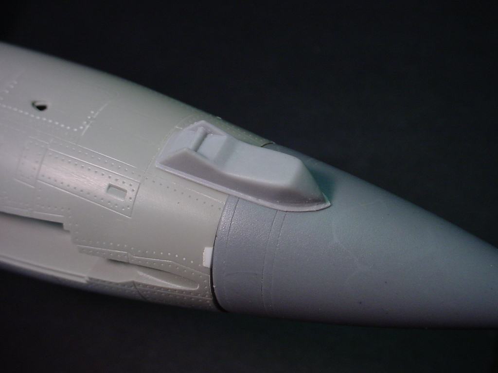
Here is the resin radome and combination RHAW antenna / strike camera balanced in
place. The parts are not glued in place which is why there is a big huge gap between
the radome and fuselage.
 Here is a photo of the inside of the top half of the right wing showing the installation
of the pieces. The image to the left is a link to a larger image. Click that
thumbnail to view the large photo.
Here is a photo of the inside of the top half of the right wing showing the installation
of the pieces. The image to the left is a link to a larger image. Click that
thumbnail to view the large photo.
 |
 |
 |
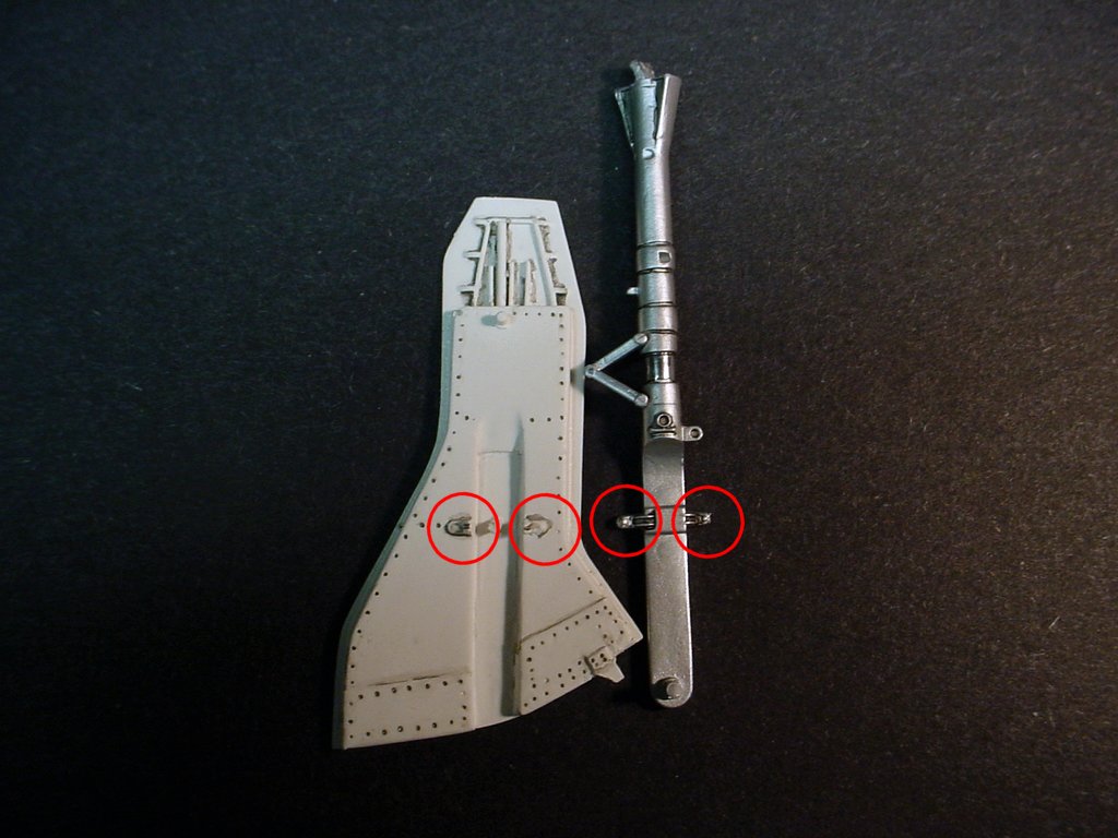
Notice in the photo to the left that both the main gear doors and the Scale Aircraft Conversions metal main gear
BOTH have the brackets that mount the gear door to the gear strut. One of the two has to go because they
both can't occupy the same space! I chose to sand them off of the gear doors and use the ones cast onto the
gear struts since that would provide a more secure mount for the doors. Note that this may not be a problem
with either the kit gear struts or another brand of metal gear, but it is a problem with the ones I used.
While you are sanding, you might as well remove the pins that locate the door onto the gear since they don't line
up properly either. The one toward the bottom of the door won't even reach the gear unless you cut the brackets
off of the gear strut and use those molded on the gear door. The one to the top is about 1/32" off of where
it needs to be for the doors to line up properly. Again, let me emphasize that this may only be an issue with
the Scale Aircraft Conversions metal main gear. I really like that cast metal gear and highly recommend it,
however it doesn't mate well with the BlackBox main gear doors.
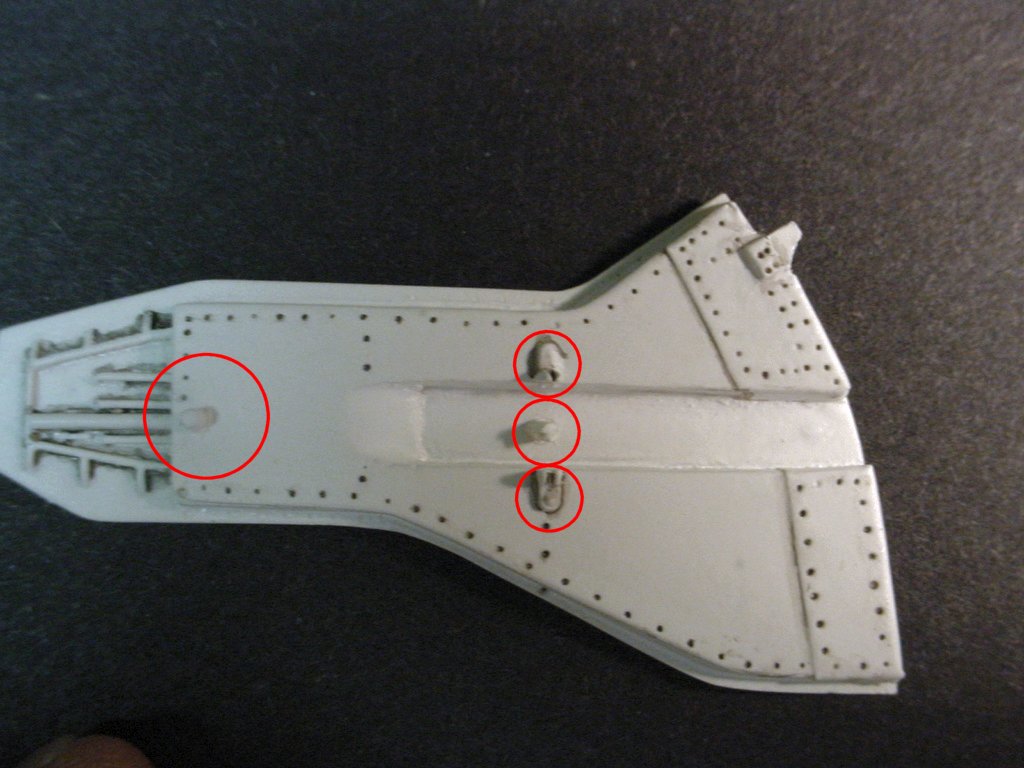
|
If you choose to use the brackets on the gear struts you need to notch them down. The strut should recess down into the gear door. The photo to the left doesn't show it very well but I did file the brackets down very thin so that the strut would fit down into the door. I also redrilled the location for the upper mounting pin so that it lined up with the hole in the strut and used a short piece of 0.025" styrene rod to mount the door there. In reality, this is wrong. The real gear door could not mount at the top and bottom of the strut or the oleo strut would not be able to expand and contract. If you choose to omit the top mount the gear will be more correct, however the door will be very fragile as well. The only thing holding it will be the two very small spots of glue on the brackets at the bottom. |
|
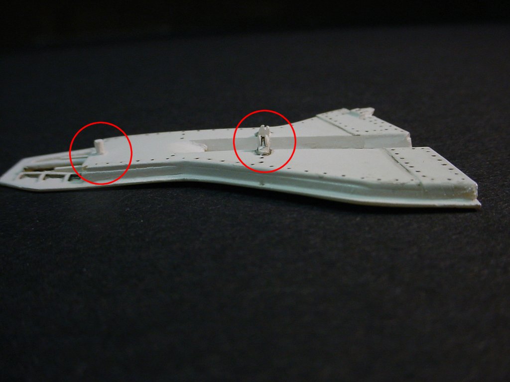
Here is mine ready for further detailing. It will now get the brake and electrical lines added as well as the landing light that mounts on the gear strut. I think I'll clean up some of the "Dirt" I left on the edges of the gear door as well ;) Fixing the problem, even with the gear strut and door already painted, was not a major task and only took about an hour to do both sides. It would have been a lot easier to fix the problem if I had noticed it prior to painting everything because I had to be very careful not to scratch the paint while cutting and sanding the struts and doors. |
CUTTING EDGE CEC32014 M117 750lb BOMBS
_lb_Bombs_(4)++Wed_08_31_200520_0_36.dat+14.99+)
This resin set provides a complete replacement for the M-117 bombs in the kit. When used in conjunction with the Eduard 32208 F-105 Thunderchief Armament Set the result is some highly detailed replicas of the M-117 750 pound general purpose bomb.
|
The set contains four complete bombs in the package, and each bomb consists of seven pieces as shown in the photo to the left. A nose section, a tail section, four fins, and your choice of a nose fuse or nose plug. Note that the casting plug has been cut from the nose and tail sections for this photograph. They are not difficult to cut off, just put a razor saw right against the shoulder where the plug joins the part, saw a little bit, rotate the part, saw a little more, and repeat. Keep the saw right against the shoulder and the parts will cut rather cleanly. |
|
The only problem I ran into assembling them was that the nose section of most of the bombs was not cast square. As can be seen in the photograph the 90� triangle does not line up with the edge of the bomb. It isn't a real serious problem, it just takes a little sanding to correct. At first I thought it was the way in which I was cutting them from the casting plug, but when nearly all of them were the same way and the tail sections weren't I decided it wasn't me. |
|
Here is one that is roughly primed. I wanted to see how much of a gap I had to fix between the fin and the tail, and judging from this photo I still need to do some work on it. Also notice that the gap between the front section and tail section is completely gone. The real ones show a panel line there as can be seen on This Photo Of The Real Thing on GlobalSecurity.Com's web site (an excellent resource for ordnance photos, by the way!) so I will probably go back and scribe a panel line on them. I prefer to do that than try to maintain an even panel line depth when gluing parts together at the panel line. |
|
I didn't like the way the decals fit the bombs so I decided to paint the yellow nose stripe. Masking around a curve
such as the nose of a bomb is not the easeiest thing in the world to do but with a little time and effort it can be
done. The photo to the left shows one bomb masked (top of the photo) and a second with an initial coat of light
gray primer. I have never found yellow paint that covers very well so if the base color is dark I always spray a
coat of something light in color before the yellow.
To mask them two pieces of tape are needed, and they need to be cut on an arc. For these particular bombs the piece to the rear was cut on an arc with a 0.740" diameter and the one at the front was cut with a 0.520" radius. The stripe is 3/32" in width, the masking tape at the rear is 5/32" from the nose and the piece at the front is 1/16" from the nose. |
Here's a hint for sanding the halves: Place a piece of sandpaper on a hard surface (I like to use flat ceramic tiles), then sand the part in a figure-8 motion across the sanepaper. If you do this you won't get a rounded or off-center end, it will be nice and smooth and even. Unfortunately the photo of the nose section in the middle photo above doesn't show that very well. If you look where it is sitting on the ceramic tile you can see a slight gap on the left side and it should be completely flat on the surface. I haven't assembled that one yet so I need to work on it a bit more. However, as can be seen in the photo of the assembled bomb above it is so even that when the parts are glued together there is hardly any gap at all. I used 2-part epoxy to glued the halves together, by the way. Once it cures it sands quite easily and conforms very well to the shape of the bomb.
GENERAL ASSEMBLY ......
LEADING EDGE FLAPS
The leading edge flaps are somewhat problematic. Specifically, they fit really
badly. You can see what I mean in
This Photo of the F-105G I built last year. Keep in mind that the photo was
taken after messing around with them for a good while getting them to fit that well.
I've decided to change tactics on this "D" model. The parts are the same as on my
"G", but this time I chose to leave out all of the hinges and pins that Trumpeter
provides because they cause a good bit of the fit problem. The flaps are designed
to pivot, but I wound up gluing them closed on my "G" and this one will be built with
them closed as well. I also closed off the back of the assmblies with a piece of
0.020" styrene sheet 5 5/16" long x 3/16" wide at the inboard end and 1/16" wide at the
outboard end. The flaps are hollow but there is a ledge inside the back that the
strip of styrene fits into quite well. I used a styrene pin in the middle of the
rear of the flap (a piece of 0.025" styrene rod) drilled through the backing and into
the leading edge of the wing to hold things in place and then glued it using Tenax
7R. I still had to do some sanding and then escribe the line between the flap
and wing, but all in all it worked much better than on my "G" model. A couple of
photos are included below, but I still need to do a little cleanup on the
joint. As can be seen in the photos there is a bit of a gap on the bottom side
of the wing but there may actually be one like that on the real thing.
The five small spoilers at the rear of the wing
look like they are sticking up in the photo but they are not, they are dead flat with
the surface of the wing. I'm going to have to go back and rescribe the panel lines
between them and the wing because the sanding completely eliminated most of them.
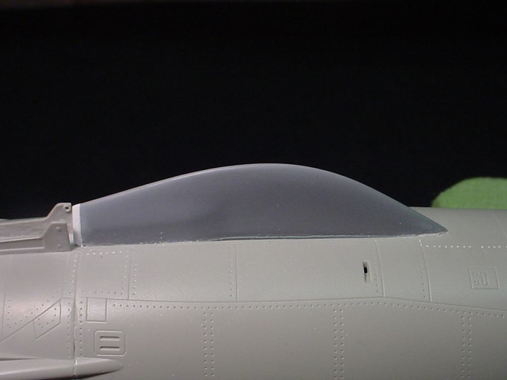
INTAKES
I could probably have left the seam there since there is a track for the intake plug
that runs right down the centerline of the intake, but I would have known it was a seam
and I plan to do something different for the intake plug track.
 The intakes have an evil seam on the inside where the two wing halves join. It
is about 1/16" wide and pretty deep, and even Tenax 7R glue didn't help very much. A
little bit of putty using
Matt Swann's "Fence" Method
followed by some sandpaper wrapped around around a wooden dowel makes pretty short work
of them though. As can be seen in the photo, all that is left of the seam is a
reflection and some white putty that will disappear when it is primed. Just be
sure to take care of it before installing the wing on the fuselage, it is a LOT harder
to fix then (I made that mistake on my "G" last year!).
The intakes have an evil seam on the inside where the two wing halves join. It
is about 1/16" wide and pretty deep, and even Tenax 7R glue didn't help very much. A
little bit of putty using
Matt Swann's "Fence" Method
followed by some sandpaper wrapped around around a wooden dowel makes pretty short work
of them though. As can be seen in the photo, all that is left of the seam is a
reflection and some white putty that will disappear when it is primed. Just be
sure to take care of it before installing the wing on the fuselage, it is a LOT harder
to fix then (I made that mistake on my "G" last year!).
COCKPIT PROTECTION
On this particular model the nosegear is also easily damaged since it has to be installed
before the fuselage is closed up. I have a similar cover for the nosegear but it was
off when the photo was taken. This nosegear is metal so it won't break easily but
the paint is aluminum metalizer and is somewhat fragile.
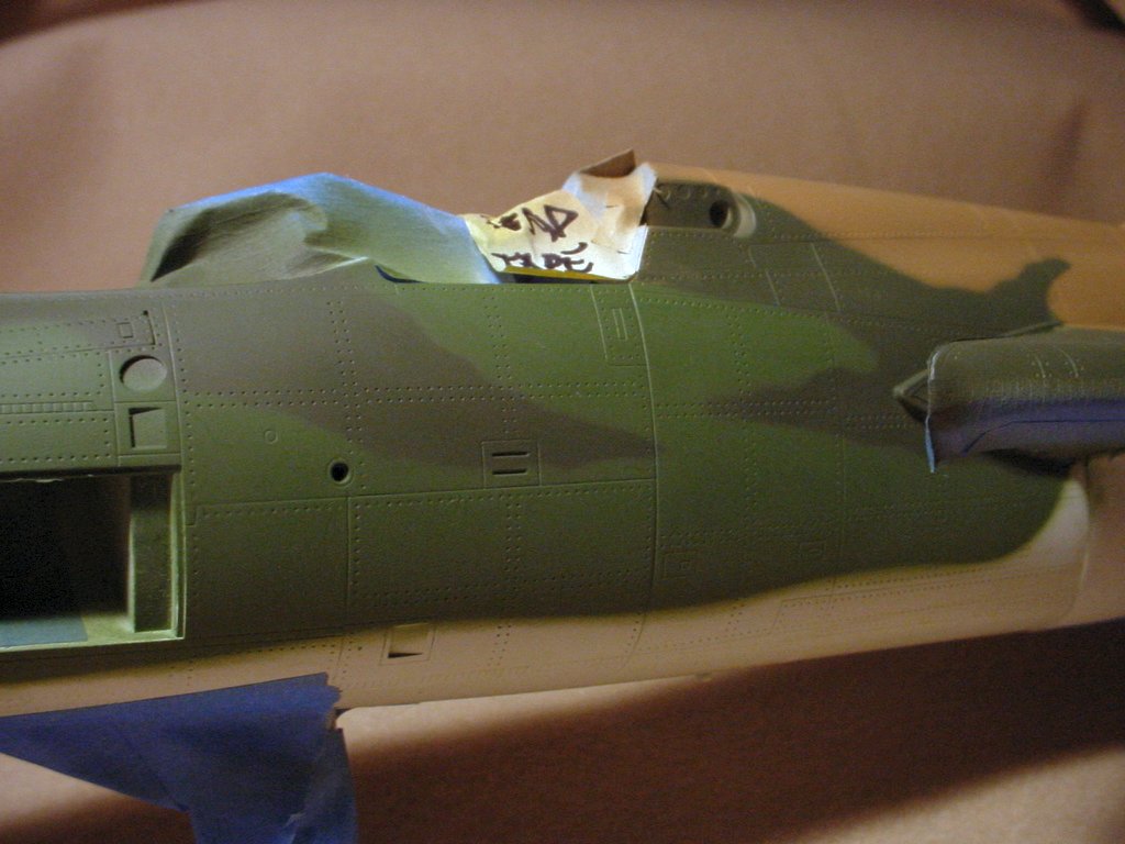
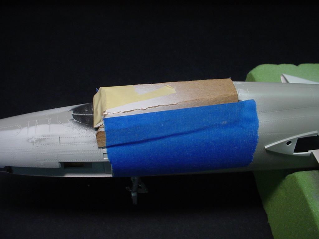 Once the fuselage is assembled the cockpit presents a rather delicate assembly that
is just looking for a chance to get broken. This is the method I use to protect
them during assembly. I cut a piece of stiff cardboard and bend it to fit over
the cockpit area and tape it in place. It's quick and simple and goes a long way
to help prevent damage to your cockpit.
Once the fuselage is assembled the cockpit presents a rather delicate assembly that
is just looking for a chance to get broken. This is the method I use to protect
them during assembly. I cut a piece of stiff cardboard and bend it to fit over
the cockpit area and tape it in place. It's quick and simple and goes a long way
to help prevent damage to your cockpit.
LANDING GEAR
This is a large and heavy model when completed, and I don't think that the plastic landing gear provided in the kit
is strong enough to hold it up. It might last for a while but I suspect that over time they will begin to
bow. To be honest though I never even tried them. I used metal gear for the
F-105G I built in 2004 as well as this one. If anyone has built this model and used the plastic gear I would
be interested to know how well it has held up, and will be glad to add your comments to this page.
Personally I strongly recommend that anyone building this model invest in a set of cast metal landing gear, it is
well worth it. There are two companies I know of that provide these parts:
Scale Aircraft Conversions (available from Meteor Productions) and
Aeroclub Models. The Scale Aircraft Conversions set
contains the main gear only whereas the Aeroclub Models set includes all three gear struts. There may be other companies
that provide these parts but these are the only two that I am aware of.
WEIGHT AND BALANCE
This model will be a tail-sitter if you don't pay attention to what is going on! The instructions, Page 9, Section 16,
incicate that 110 grams of weight (3.88 ounces) need to be added to the nose. With all of the resin I added to the
rear of this model I added about 6 ounces of lead to the nose to be safe. From everything I can tell so far it will
be fine, but I'm leaving the nose cone off until the very end so that I can epoxy some more lead in the nose if I need to.
This additional weight also emphasizes the need for stronger landing gear, especially the main gear. See the
paragraph above pertaining to the landing gear.
|
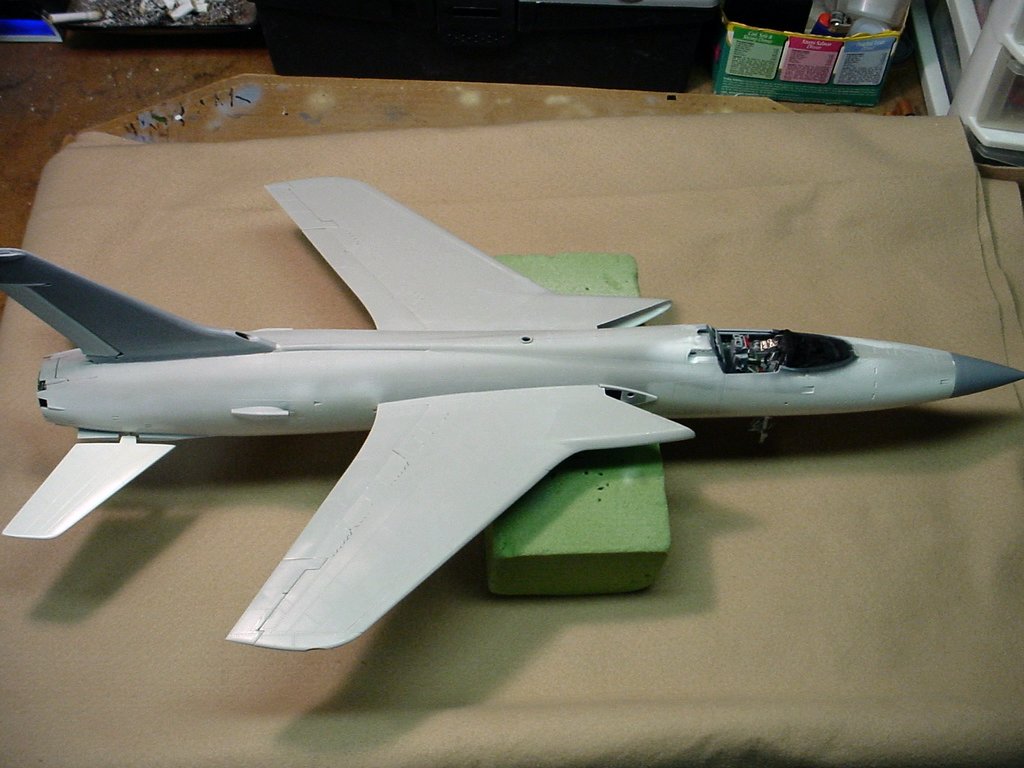
JANUARY 3, 2006 -- GENERAL CONSTRUCTION PHOTOGRAPHS
| ||
 |
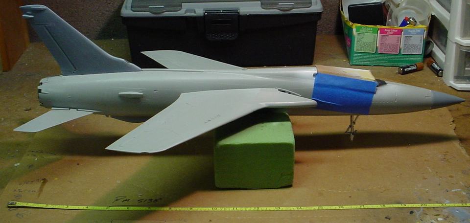 |
The images are links to larger photographs. Click the image to view the larger image |
|
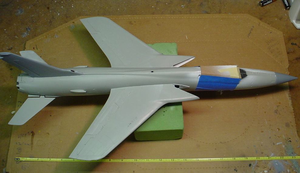
Above are a couple of progress photos. The rudder, horizontal stabilizers,
and radome are not glued in place, they are just stuck there to try and get a feel for the balance
of the model so far. I have nearly 5 ounces of lead in the nose and it is balanced on the
block of green foam underneath it so it should be relatively close.
I have a good bit of work to do on the seams where the wings join the fuselage. Because of the way the Blackbox wheel wells installed (and because I refused to cut a chunk out of the intake so they would fit the way Blackbox thought they should) I wound up with a slight seam where the wings mount. Nothing major, but something I have to fix. I also popped the seam apart in the middle of the top of the fuselage when I was installing the wings (I squeezed it too hard!). I sent an email to the owner and told him that I don't give a damn what they say about "Stealth" and "Mission Capability" or any of the other modern buzzwords, there is nothing as sexy looking (As far as jets goes ;)) as some of the Vietnam era planes. That Coke-bottle fuselage, and the graceful curve from the trailing edge on one side through the fuselage to the other side. All of it topped by that big 8' vertical stab. And, of course, those distinctive intakes. The 105 was a beautiful plane by any standards, and I'm jealous as hell of the guys that got to fly them ;) | ||
|
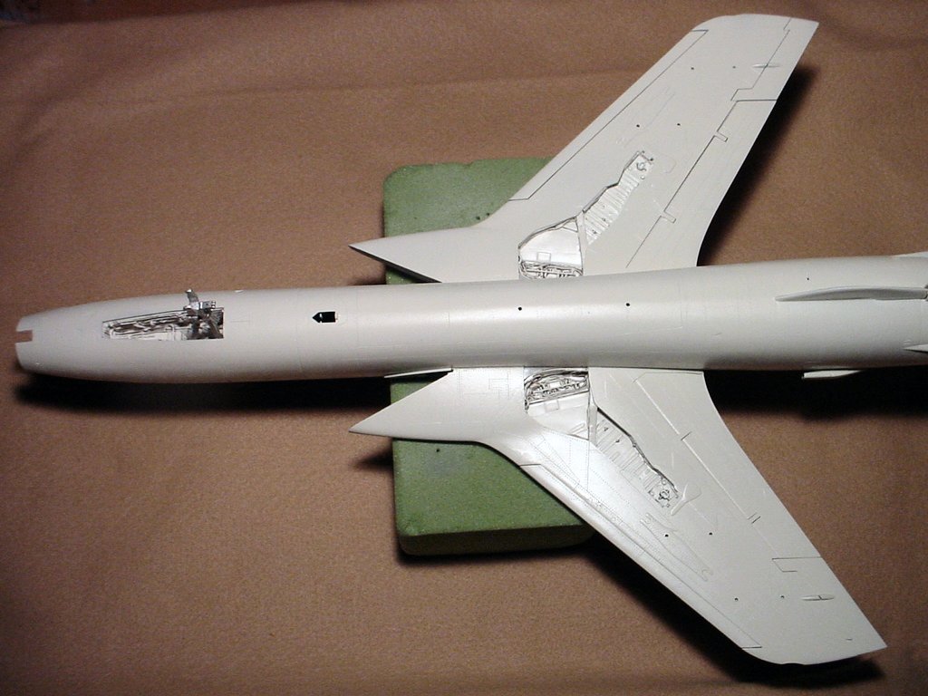
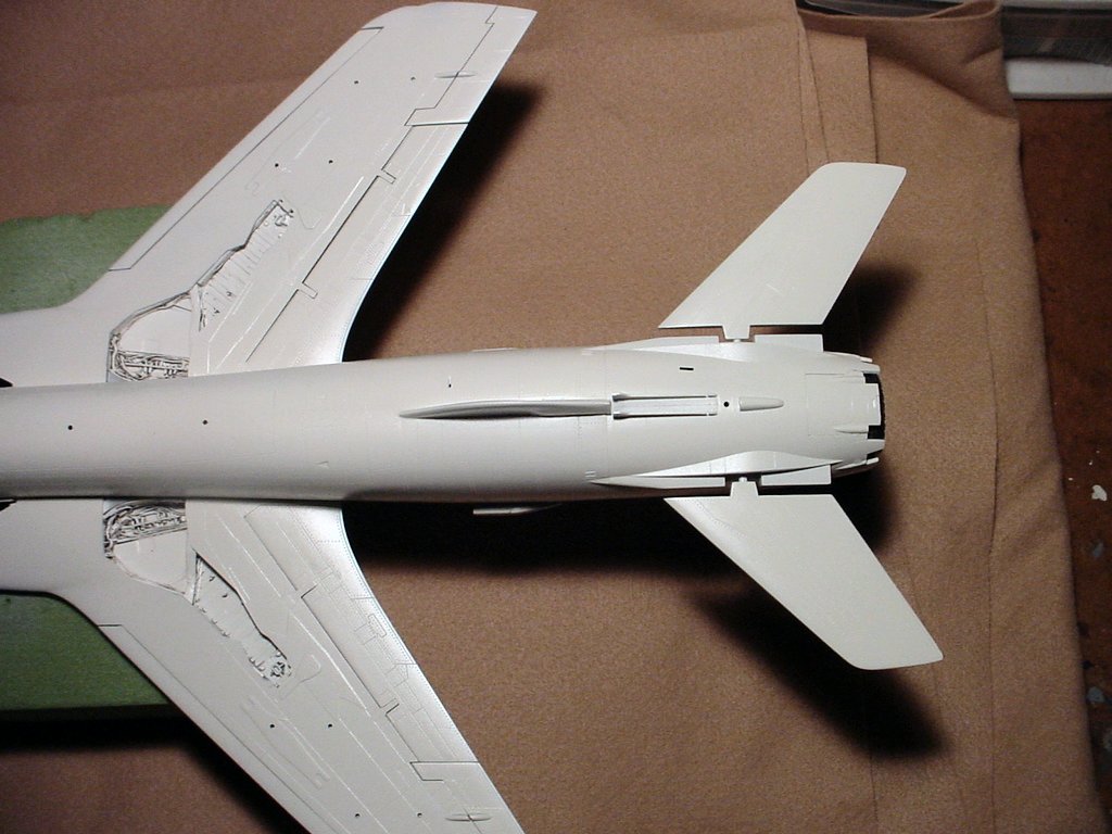
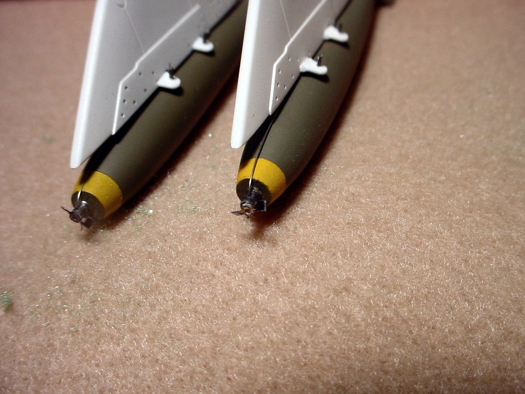
MARCH 4, 2006 -- GENERAL CONSTRUCTION PHOTOGRAPHS
| ||
 |
 |
 |
 |
 |
 |
|
I have been working on it, just not steadily. It has been COLD in Tennessee off and on for the past couple of months and I haven't gotten a lot done. Paint doesn't spray well when it is cold, and my basement is unheated. I can keep warm, I can get the parts and paint warm, but I can't do much about the cold air that makes my airbrush work! Note that the rudder, stabilators, and nose cone are not glued in place yet which is why they have large gaps in the photos. I just stuck them in place for the photos. Likewise, the glare panel in front of the cockpit and the ejection seat are not yet glued in place. The main fuselage is assembled and the bottom has been painted in its off-white color, and has a coat of clear gloss on it. The clear gloss will eventually get covered with a coat of clear flat but I need gloss for the decals. There is intentionally no panel line wash at the owner's request. I've also finished some of the smaller detail items such as the MK-82 bombs and pylons, the underwing fuel tanks and pylons, and some of the M-117 bombs. The MK-82's are shown above. The propellers on the fuses are part of the Eduard photoetch armament set and the arming wires are just small diameter wire. The yellow band o nthe noses that denotes live ordnance is not a decal, it is painted on. I couldn't get the decals to fit properly so I just decided to paint the bands. About all that is really left to assemble is the centerline MER, some of the M-117 bombs, and the main landing gear. I also have a few gaps here and there I need to fix and some minor parts such as the tail hook, speed brake petals, canopy, etc., but most of what is left at this point is painting and decaling. For that I need some warmer weather, but that should happen in the next couple of weeks. | ||
|
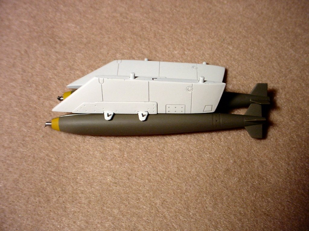
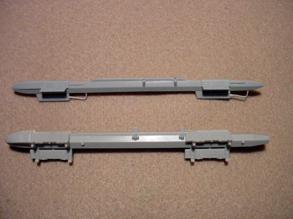
CENTERLINE MULTIPLE EJECTOR RACK
| ||
 |
 |
 |
|
The Trumpeter Multiple Ejector Rack (MER) has some problems. Photograph 1 above shows the Trumpeter MER on top and an extra MER from my Tamiya F-4E on the bottom. As can be seen the Trumpeter MER is much thinner and just less "Bulky" than the Tamiya MER. Photo 2 shows another problem, sort of. The photograph is terrible since I caused my camera to focus on the clamps holding the parts instead of the noses as I needed to show. The Trumpeter MER has the bomb attachment set at 90 degrees, or square with the bottom bomb. The Tamiya MER has the bomb attachment angle set at approximately 60 degrees. The Trumpeter MER also didn't have sway braces for the bombs and, since they have large tabs to attach the bombs instead of pins, it would have been difficult to add some (there are plenty in the kit). From the photos I've looked at, and after swapping a couple of emails with the man I'm building the model for, it was decided that the Tamiya MER was more accurate so that is the one that is being used. Photograph 3 shows the completed assembly ready to go on the plane. The adapter pylon on top of the MER itself is the Trumpeter pylon. The spacing of the attachment points was different between the Trumpeter pylon and the Tamiya MER by about 1/4" so I had to plug the front slot on the Trumpeter pylon and cut a new one to match the Tamiya MER. Photograph 3 also shows two thin pins sticking out the top of the pylon. Those are 1/32" steel music wire. They are epoxied into the MER and go all the way through the pylon. I drilled matching holes in the bottom of the fuselage and will epoxy the pins into the fuselage. It is going to have to carry 6 resin M-117 bombs and I did not want to take a chance on it coming loose. The epoxied pins in addition to the normal styrene glue should hold it quite well. The assembly was finished in Testors Model Master Aluminum Metallizer. Notice that both the MER and the pylon are painted that color. According to the man I'm building the model for an aluminum color on that pylon was the most common although other colors were used. He said that they were also frequently painted to match the bottom of the jet and even painted black on occasion. I'll pass on a little tidbit that I got from the man I'm building this one for. The bombs on the bottom of the centerline MER should be oriented so that the fins form an "X" whereas the bombs on both of the shoulders should be oriented so that the fins form a "+". This helps prevent them from fouling each other when released. | ||
|
MARCH 19, 2006 - GENERAL CONSTRUCTION PHOTOGRAPHS
| ||
 |
 |
 |
 |
 |
 |
 |
 |
|
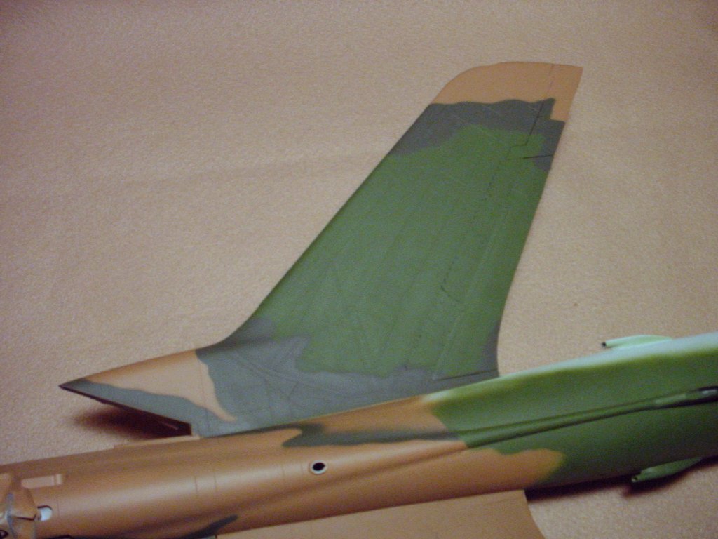
|
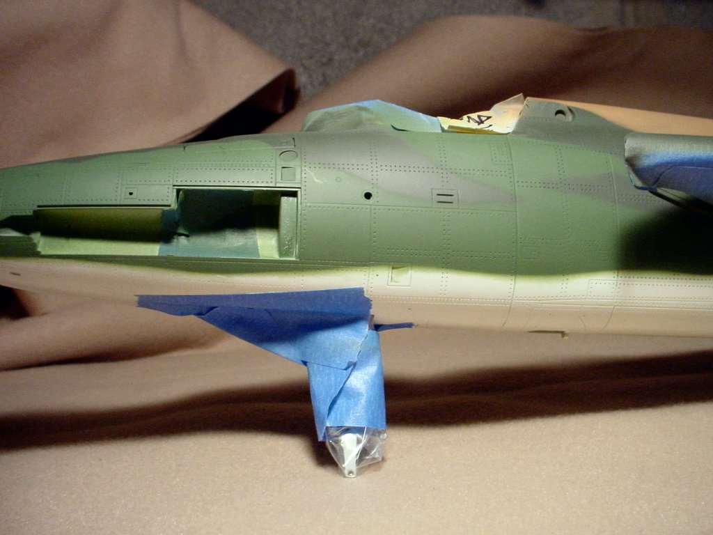
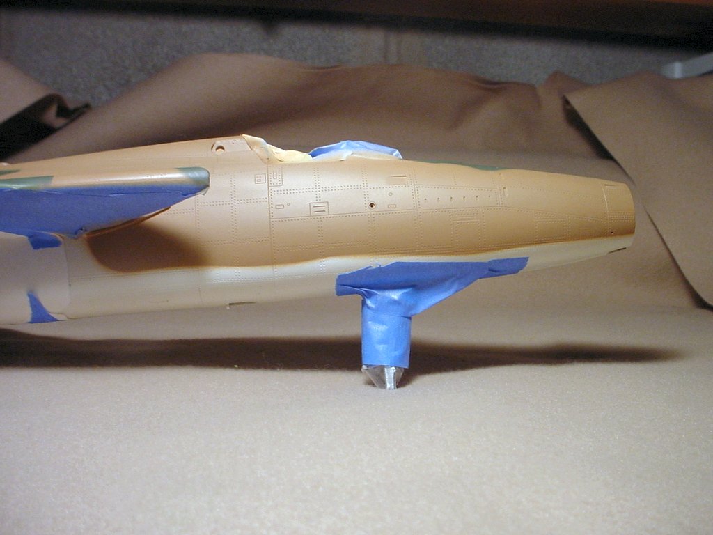
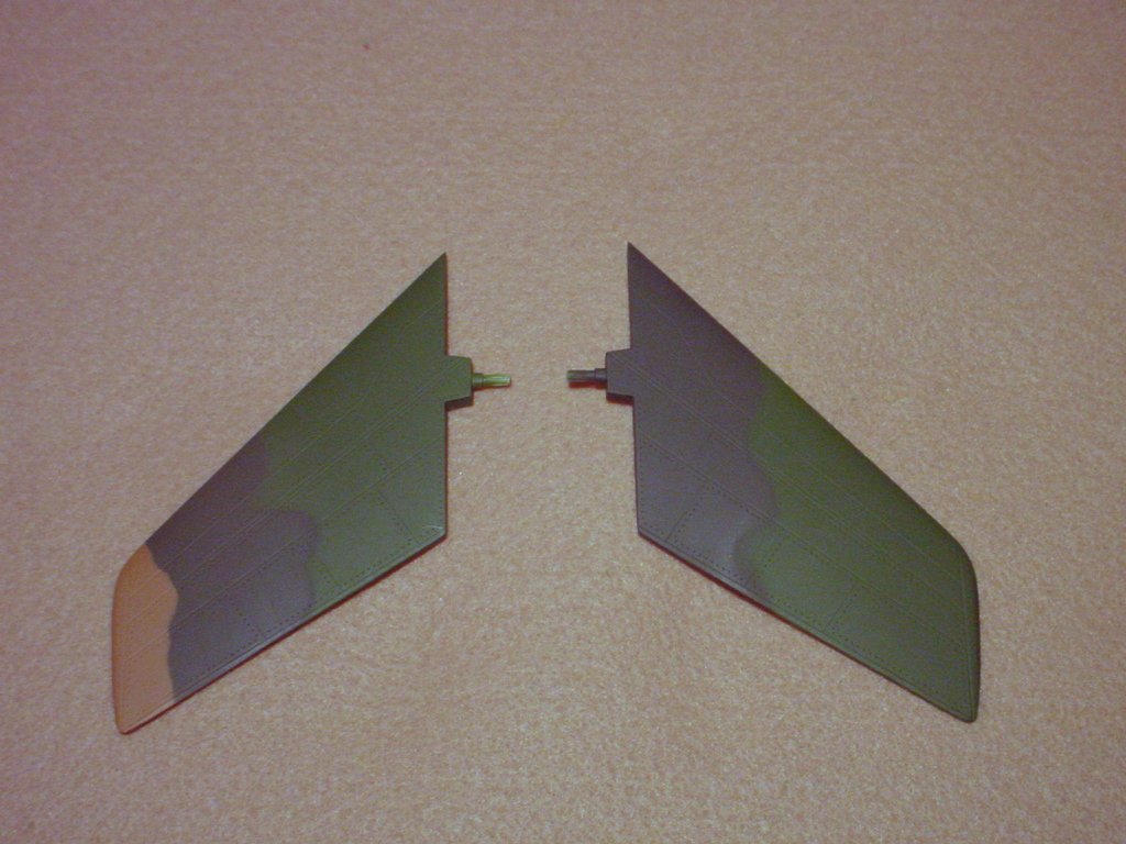
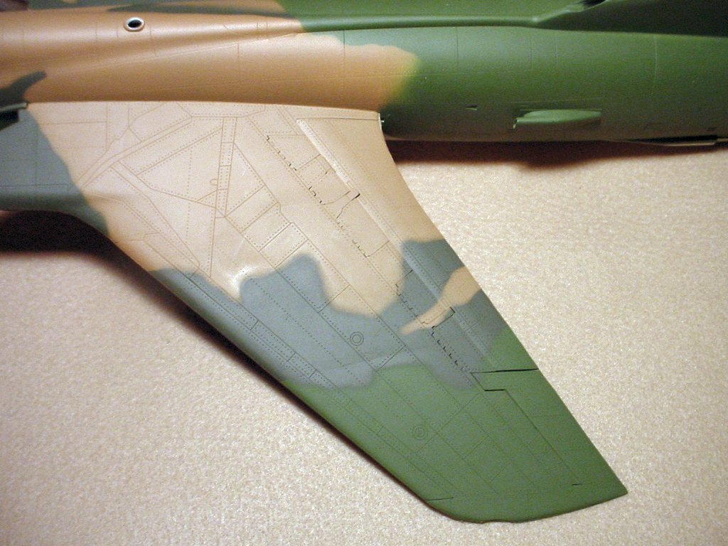
The camouflage painting is well underway but not complete. The photos above show what has been done so far, but keep in mind that nothing behind the wings is complete. There are also a couple of sections on the top and on the left side over the wing that aren't complete. The photos look somewhat dusty and grainy in places but the model doesn't look like that. I suspect that is some residue from my photo "Cleanup" with Paintshop Pro. The colors in some of the photos aren't exact either. Photo #4 shows the brown most correctly and photo #7 shows the two green shades most correctly. If you wonder why the piece of tape over the cockpit reads "Bad Tape" it's because it isn't stuck to anything and I didn't want to trust it to block any overspray. I apparently poked my finger through it and shoved it down into the cockpit. I lifted it back out with some tweezers but didn't want to push on it too hard to get it to stick back. The cockpit is very fragile! Luckily all the painting up front was done when it happened. | ||
|
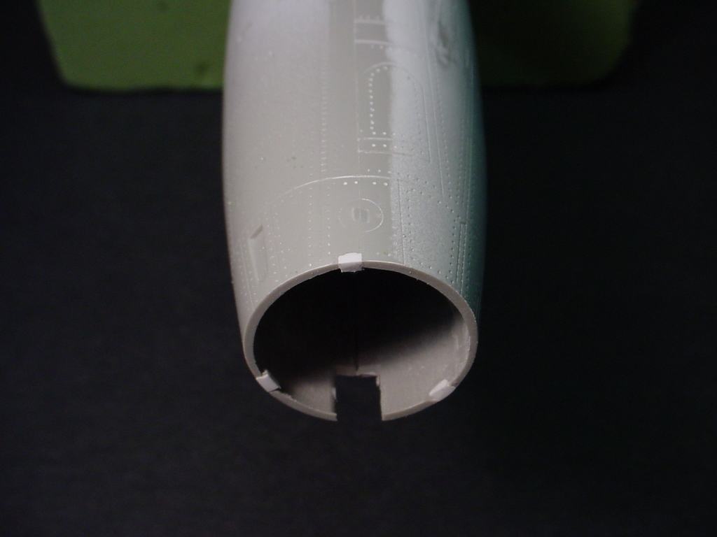
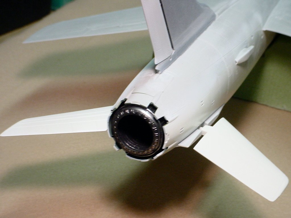
MARCH 26, 2006 - SPEED BRAKE PETALS
| ||
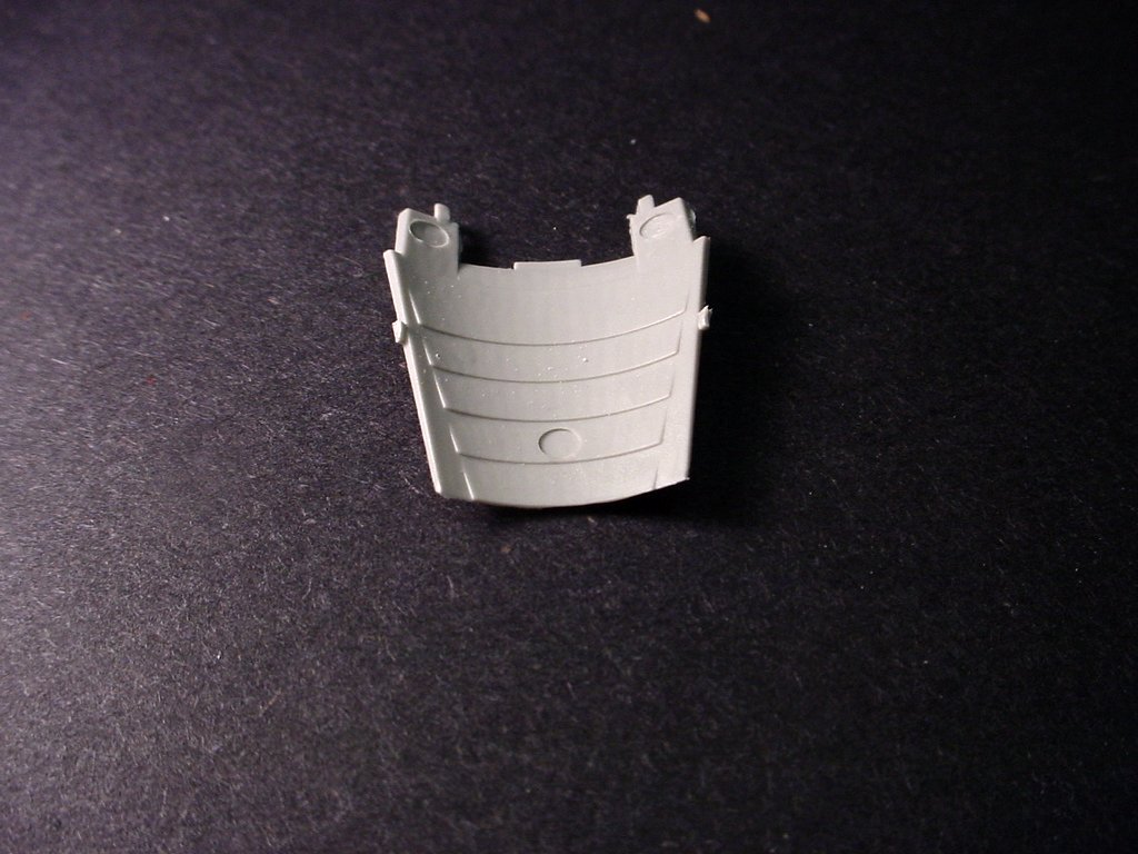 |
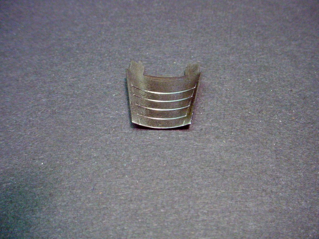 |
|
|
The photos above show one of the four speed brake petals (part I-8) that fit around the exhaust end of the engine. Look closely and you'll see a problem with them (click the images to see a larger photo). The photo on the left shows three very prominent ejector pin marks; two at the front (top of the photo) and one in the middle towards the rear. When the engine is shut down and the hydraulic system loses pressure the speed brake petals tend to open up. The top stays down, the sides open about 7 degrees, but the bottom petal flops wide open. If you don't fix those pin marks they will be very visible on the bottom section, especially the one toward the rear. The two at the front are easily sanded off but the third one needs to be filled and sanded. It doesn't take much work and certainly improves the appearance of the model, as can be seen in the photo to the right. | ||