| DOOR PANEL REMOVAL ..... | |
|
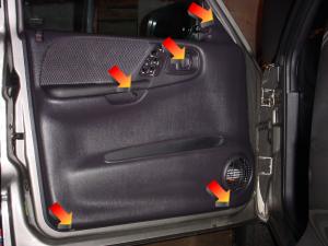
FRONT DOORS -- Step 1
There are four screws holding the right door panel to the door itself and five on the left side panel. Two are
at the bottom of the door panel, one is behind the latch handle, the fourth is sort of "Inside" the grab bar on the
door, and the fifth is above the outside mirror adjuster. The arrows in the accompanying photo point to the five
locations.
Update - 05/04/09 - I had originally indicated that there are four screws on the left door, but have since gotten a
couple of email messages from other owners that corrected me. There are five screws on the left door. Thanks
for the input, Matt and Walter.
|
 |
|
FRONT DOORS -- Step 2
Once the screws are out lift straight up on the door and it will disengage from several slots in the door.
DO NOT try to move it very far yet! Lift it up and lean away from the door enough so you can see behind it
and get your hand in there. Unplug the connector for the windows and door locks. The passenger side connector
has a clip on top that you need to push down to release the connector. The driver side has a red lock that needs to
be slide out to unlock the connector so that it can be disconnected. Also, the driver side has a connector for the
power mirror controls.
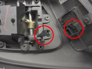
Disconnect the linkage from the door handle as well. The door handle linkage rod is secured by a plastic clip as
shown by the left-hand circle in the photo to the right. The rod is bent so that it will slide down into the middle
of the clip, and then the clip rotates and snaps onto the linkage bar itself. Just unsnap it from the rod and it will
pivot out of the way so that you can lift the rod out of the clip. These clips are "Captive" so they won't go
flying when you take the linkage rod out. When this is done the door panel can be lifted off completely and set aside.
|
 |
|
REAR DOORS -- Step 1
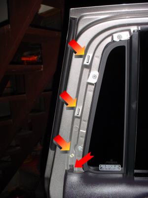
Remove the trim strip that goes up along the back edge of the door. This strip is just clipped into place.
You may be able to just pull it off (one of mine was easy, one was stubborn). The bottom has a white plastic
stud that releases relatively easy. There are two metal clips above it, but they also just snap into place.
If you can't get it to start, look at the edge of the door and pull the trim stip away from the door a little. You
should be able to see the white stud, and if you slip something in to pry with it will pop loose. DON'T use
a screwdriver or something that will scratch your paint or crack the trim strip. See if you can find a plastic
utensil in the kitchen you can "Borrow" for a few minutes (if it breaks just pretend it never existed!).
The locations of the white stud and the two metal clips (the bottom multi-color arrow shows the stud and the other
two multi-color arrows indicate the metal clips) are shown in the photo to the right. The photo also indicates with
the solid red arrow the location of the fifth bolt (described in Step 2 below) that is not present on the front doors.
|
 |
|
REAR DOORS -- Step 2 Now, the rear doors are very much like the front doors. The major difference is that there are five screws to remove. Two are at the bottom of the door, in the same locations as on the front, two are behind the door handle and "Grab Bar", just as they were on the front doors. The fifth screw is on top of the door and was covered by the trim strip removed in the step above. |
|
|
REAR DOORS -- Step 3
As with the front doors, once the screws are out lift straight up on the door and it will disengage from several
slots in the door. DO NOT try to move it very far yet! Lift it up and lean away from the door enough
so you can see behind it and get your hand in there. Unplug the connector for the windows and door locks. The
electrical connectors are the same on both rear doors, and have a clip on top that you need to push down to release the
connector.
Disconnect the linkage from the door handle as well. The door handle linkage rod is secured by a plastic clip as
shown by the left-hand circle in the photo to the right. The rod is bent so that it will slide down into the middle
of the clip, and then the clip rotates and snaps onto the linkage bar itself. Just unsnap it from the rod and it will
pivot out of the way so that you can lift the rod out of the clip. These clips are "Captive" so they won't go
flying when you take the linkage rod out. When this is done the door panel can be lifted off completely and set aside.
|
|
| SPEAKER REMOVAL ..... | |||||||||||||||||||||||||
|
Step 1 .....
You can see the thick spacers that the speakers are mounted on. Before you remove them MARK THE TOP OF THE
SPACER! Since most aftermarket speakers have some arrangement of coaxial speakers or logos or something that
needs to be relatively horizontal or straight up and down, be sure and mark the top dead center of the spacer so that
you will know where it is. Since the front spacers are black, put a piece of masking tape on the spacer and mark
on that. The rear spacers are gray (at least on my truck) so they are no problem.
The photo shown here is the left rear door. The spacers on the rear doors are somewhat thinner than those on the
front doors, and they are also angled upwards. This photo is of the finished installation and shows one of my Polk
Audio EX365 speakers.
|
 |
||||||||||||||||||||||||
|
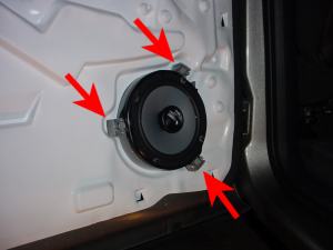
Step 2 ..... The spacers are held on by three long screws (indicated in the photo above). Remove them and the whole assembly will come loose from the door (the speakers are clipped into the spacers so they won't fall off). |
|||||||||||||||||||||||||
|
Step 3 ..... The speaker wires have connectors on them. Press the release "Clip" and they will disconnect. The connectors will probably need to be cut off, but we'll do that later. |
|||||||||||||||||||||||||
|
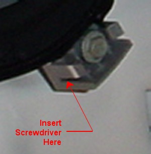
Step 4 .....
The speaker / spacer assembly has three "Tabs" around the outside, and those tabs have two clips, one on each side, that
hold the speakers to the spacers. The trick here is to release both clips of one tab at the same time so you can
get the speaker out. The easiest way I found was to use two very small screwdrivers.
Pick one of the tabs, it doesn't matter which one, and using one of the small screwdrivers, slide the blade into the
gap at the front of the clip, pry outward slightly, and then slide the scredriver up behind the clip to wedge it against
the other side. This will hold that clip out of the way so you can release the other side. Use the other
screwdriver to release the other clip on the tab, and then the speaker itself can be lifted up off of that tab.
Repeat this process for either of the two remaining tabs. Once the speaker is released from two of the tabs it
can just be slide out of the third one.
This is a whole lot easier to do than to describe. The photo shown here is a closeup of one of the tabs from
the photo above. It sort of shows the clip and where to insert the screwdriver. Once you see them you will
understand what I am getting at.
|
 |
||||||||||||||||||||||||
|
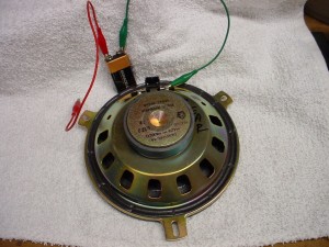
Step 5 .....
Next we need to verify the polarity of the speakers. The factory wring color codes should be as follows: You will need a 9-volt battery and a couple of pieces of wire (if you have clip leads with alligator clips on them,
you are in good shape. If not just temporarily tape one wire to each terminal of the battery.
Lay the speaker face down, and touch the negative wire from the battery to one of the two terminals on the back of
the speaker. Quickly touch the other wire to the other speaker terminal, and observe the motion of the sound cone
of the speaker. If the sound cone moves forward (down if the speaker is laying face down) then the polarity is
correct; the "+" connection of the battery is on the "+" speaker connection, and the "-" battery connection is on the
"-" speaker connection. If the cone moves backwards, reverse the two wires and try again.
When you find the correct polarity, mark it on the back of the speaker.
|
 |
||||||||||||||||||||||||
|
Step 6 .....
Now we can change the connectors in the door. The factory harness has braided tubing around the speaker wires to
prevent them from being abraded, and they are taped at the ends. Remove the tape, slide the tubing up a couple of
inches, and tape it back down. Plug the connector into your speaker, and take note of which connector is "+" and
which is "-" as was marked in the step above. (My guess is that both wires are going to be the same color, but one
is going to have a black stripe on it. The one with the black stripe is probably "-" and the other one is probably
"+", but it never hurts to check!)
Clip the wires an inch or so above the connector (to leave room to splice them back together when you sell the truck
and want to put the factory speakers back in!), and install connectors appropriate for your speakers. Most speakers
use "Spade Lugs", one of which is wider than than the other. Normally the wide lug goes on the "+" side of the
speaker and the narrow one goes on the "-" side. Check the documentation for your speakers to be sure though.
Also note that while crimp-on connectors are "OK", soldered connections are always better. If you can solder the
splices then you will bave a more electrically conductive connection than if they were just crimped. As a side
note, I prefer Radio Shack 2% Silver Bearing solder to just 60/40 lead/tin solder. That little bit of silver gives a
less resistive connection than 60/40 solder.
|
|||||||||||||||||||||||||
| SPEAKER MOUNTING ..... | ||||||||||
|
Step 1 ..... The next step is to mount your new speakers to the existing spacers. This is something that I can't really help you do, and you will have to figure it out for yourself. Both sets of speakers that I used were very simple to mount to the factory spacers. The Boston Acoustics NX-67 came with adapter rings that I mounted to the speakers and then screwed to the factory spacers. The Polk Audio EX365 did not need an adapter ring, and all I needed to do was screw the speakers to the factory spacers. Here are a few hints though: | ||||||||||
| ||||||||||
|
Step 2 ..... Now, connect the speaker wires, mount the speaker on the door, and fire up the stereo. Watch the speaker cones closely, and notive when you hear a bass "Whump" whether they move out or not. If they aren't moving OUT (not IN, but OUT) then they are out of phase and the connection on that speaker needs to be swapped ("+" to "-" and "-" to "+"). Keeping the speakers in phase with the sound and with each other is critical to making them sound right. | ||||||||||
|
Step 3 .....
If everything looks and sounds right, just reinstall everything the same way it came out. Replace the door panel
(be sure to reconnect the latch rod and electrical connections!) and you are done.
One thing to keep in mind ... new speakers are not "Broken In". They will need to be used for a while before they
sound "Right". I was terribly disappointed in the sound from BOTH of my sets of speakers, Boston Acoustics and
Polk Audio, until they had been run for an hour or two and "Loosend Up" a bit. Now they sound great and I wouldn't
trade them for anything else.
|